Network explorer
The Network explorer hierarchy shows the contents of discovered controllers (see Network explorer tree).
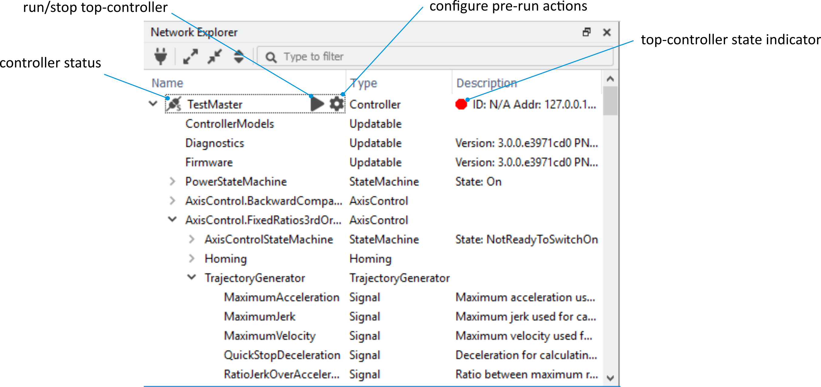
Network explorer tree
Note
This list of components is product-specific.
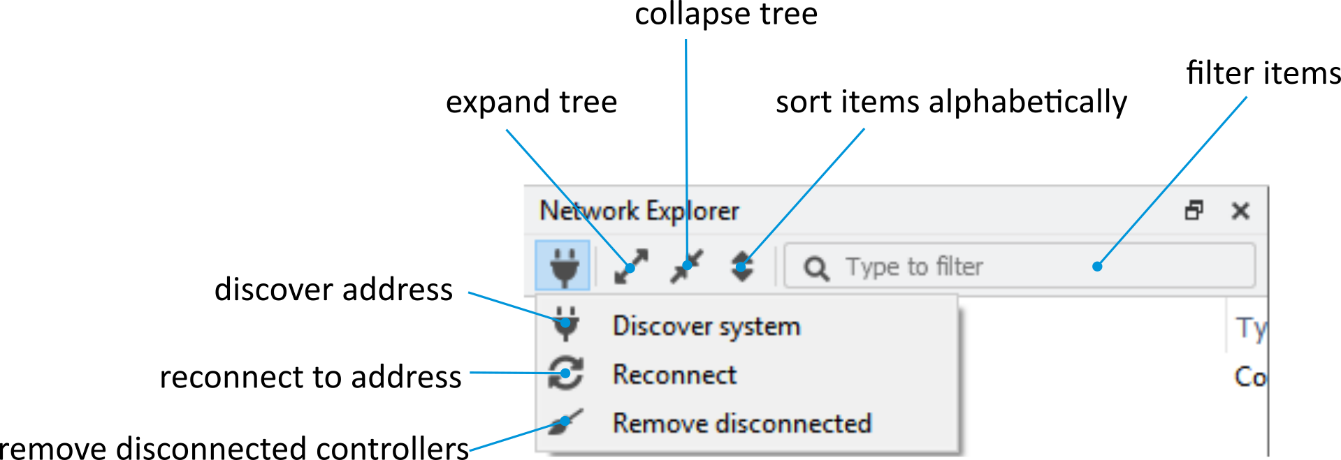
Network explorer toolbar
Sorting and filtering
Components can be sorted by name, type, or description using the ![]() icon.
icon.
Furthermore, displayed components can be filtered (via the text box with the magnifying glass icon). The filter text box supports the Perl regular expression syntax (see Network explorer toolbar).
Discovery
To connect to a different controller, click on the ![]() icon or use the menu bar IP address button as described in Discover system.
icon or use the menu bar IP address button as described in Discover system.
The controller and its content are shown in grey if the connection is lost (see Disconnected controller view):
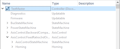
Disconnected controller view
Note
Other views will also depict PMP components in grey if their connection is lost.
Controller status icon
The controller name is prepended with an icon, which represents the controller status:
|
Controller is enumerating |
|
Enumeration successful |
|
Enumeration successful – simulated controller |
|
Connection lost |
|
Connection lost – simulated controller |
|
Controller not compatible or backup is running |
|
Controller not compatible or backup is running – simulated controller |
|
Error encountered during enumeration |
Top-controller state indicator
The state of top-controllers is indicated through the color of a circle in their status icon.
|
Top-controller is in the “Config” state. |
|
Top-controller is in the “Run” state. |
|
Top-controller is in a transition state. |


Top-controller buttons
When hovering over top-controllers with the cursor, buttons will appear depending on its state.
|
Bring top-controller to the “Run” state |
|
Bring top-controller to the “Config” state |
|
Open the pre-run actions dialog |
Pre-run actions
Pre-run actions are operations that can be configured to be executed before the top-controller is brought into the “Run” state. The Pre-run actions dialog allows for the configuration of pre-run actions for the top-controller for which it was opened. The following types of actions can be configured:
Load configuration – Loads a configuration on the selected top- or sub-controller. If variants are available, their value can be selected as well.
Apply model – Applies a model to one or more sub-controllers
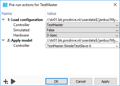
Dialog to configure the pre-run actions for a top-controller.
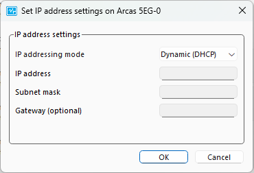
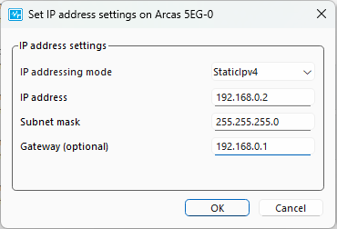
Configure IP settings
The IP configuration can be set using the Set IP address settings dialog. The actual IP configuration is shown when opening the dialog and you can select between and . When selecting , the fields , and optionally can be filled according to IPv4 protocol. Before the new configuration is active, the controller needs to be rebooted (see Reboot).
Functionality components
The component types that have specific functionality (displayed in the associated context menu by right-clicking on the item) in the PMP Tooling are elaborated below.
Controller
The properties of a controller and its sub-controllers can be displayed by right clicking the controller name and selecting in the context menu. This opens a controller properties dialog (see Controller properties dialog).
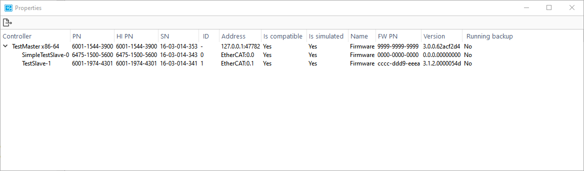
Controller properties dialog
The Controller properties dialog can also be used to export a .csv file containing the properties of all controllers in the dialog.
Reboot
The controller can be rebooted by clicking in the context menu, and destroyed by clicking (see Controller reboot).
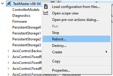
Controller reboot
Create matrix
Right-click on a controller and click on to create a matrix (see Create matrix dialog). See Template for instructions on how to instantiated a template.
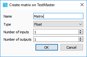
Create matrix dialog
Create template
Right-click on a controller and click on to create a template (see Create template dialog).
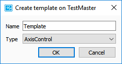
Create template dialog
Load configuration file
Configuration files are .xml files used to define the structure and properties of a controller.
For example, writable signals, e.g. jerk constraints, can be set in a configuration file.
A configuration file can be loaded by right-clicking on the controller in the Network explorer and clicking .
In case the configuration file contains variants, a dialog is shown where the desired configuration can be specified (see Configuration variants dialog).
For further details on how to use configuration files, see XML definitions.
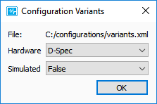
Configuration variants dialog
State machine
AxisControl states can be changed with the State machine view.
Updatable
An Updatable is essentially a large data block that can be uploaded or downloaded. Examples of updatables are firmware or injection data. Updatables can be uploaded or downloaded by right-clicking them in the Network explorer and clicking or . The progress of a transaction can be monitored via . This view opens automatically when uploading or downloading a firmware, see Updatables.
Note
After a firmware update, reboot the controller by right-clicking the controller in the Network explorer and selecting from the context menu (see Controller reboot). Some controllers do not require a reboot after a firmware update, see product-specific documentation for details.
Signal
In PMP, a signal represents a parameter or variable. The value of a signal can be monitored via the Signals view or the Scope view. Each signal is specified as either R (Read) or R/W (Read & Write). If a signal is R/W, the value of the signal can be changed in the Signal view.
Latch
A latch has a trigger source and, when triggered, stores a value from a specified data source (see Latch configuration dialog). A latch can be configured as a one-shot (disabled after the first trigger event) or in continuous mode (latch is re-enabled after each trigger event). The PMP Tooling can monitor signals and events of latches.
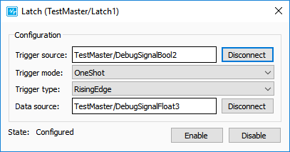
Latch configuration dialog
Event
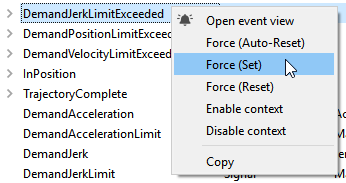
Events can be triggered when, for example, a trajectory is completed, a latch is triggered, actuator overcurrent occurs, etc. A response can be attached to an event, and the response function is called when the event is triggered. Each event has a signal that indicates if an event is active, see Event properties.
The event can be manually forced by right-clicking on the event:
Force (auto-set). Set the event active, and automatically reset it to inactive.
Force (set). Set the event active.
Force (reset). Reset the event inactive.
Event properties
Template
A Template defines an entity that can be created in PMP. A template can be instantiated at a controller or an axis control. There are three different dialogs in the PMP Tooling for creating a template, depending on the template type.
Axis control (see Instantiate AxisControl dialog):
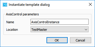
Instantiate AxisControl dialog
Axis control group (see Instantiate AxisControlGroup dialog):
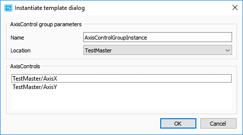
Instantiate AxisControlGroup dialog
Default (see Instantiate template dialog):
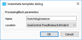
Instantiate template dialog
ProcessingBlock
A ProcessingBlock consumes data from its inputs, processes it, and produces output on its signals. It can be configured via a dialog, which can be opened by right-clicking on the processing block (see Configure processing block dialog network).
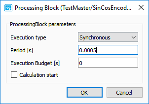
Configure processing block dialog network
Filter
A Filter provides the ability to configure discrete-time filters using continuous-time parameters. It can be configured via a dialog, which can be opened by right-clicking on the filter (see Filter configuration dialog).
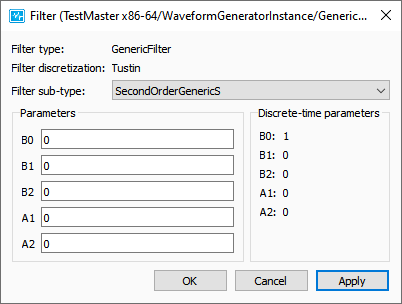
Filter configuration dialog
Alignment
For an actuator that supports alignment, the PMP Tooling offers an interface to start an alignment sequence. To align the actuator, expand the actuator shown in the Network Explorer, right-click on Alignment and select . This opens the dialog shown in Alignment of actuator dialog. An alignment method can be selected from the drop-down menu, and the actuator is aligned by clicking Start. The alignment dialog will show State: Aligned if the alignment command has been communicated with the controller. This does not indicate whether the physical alignment was successful.
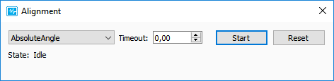
Alignment of actuator dialog
AxisControl
Right-click on an AxisControl and click to create a parameter set (see Create parameter set dialog).
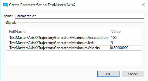
Create parameter set dialog
ParameterSet
A parameter set contains signals and values. The parameter set can be applied by right-clicking on a ParameterSet and clicking (see Apply ParameterSet).
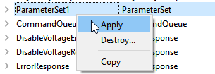
Apply ParameterSet
Homing
For an axis control that supports homing, the PMP Tooling offers an interface to start a homing sequence. To home the axis control, expand the axis control shown in the Network Explorer, right-click on Homing and select . This opens the dialog shown in Homing of axiscontrol dialog. A homing method can be selected from the drop-down menu, and the axis control is homed by clicking Start.
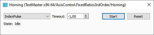
Homing of axiscontrol dialog