Simulink code generation
Introduction
PMP provides a MATLAB / Simulink toolbox that exports Simulink models to the motion controller and drives. This makes it possible to implement custom functionality that is executed in real-time. The toolbox uses Simulink Coder to generate code from the Simulink model, and adds PMP-specific wrapper functionality that allows the motion controller to interact with the generated code. From the Simulink model it is possible to create signals, inputs, updatables, events and filters in PMP. Typical use cases are control loops, compensation algorithms, coordinate transforms and custom state handling.
Since control design is often performed in MATLAB / Simulink, Simulink code generation fits well into a typical development process:
A control engineer sets up a control loop in Simulink with a plant model and a controller implementation. This simulation is a great tool to get insight in the control system and try new ideas.
Using Simulink code generation both the controller implementation and the plant model are exported. They can then be integrated into a PMP simulator so that also the software integration can be tested.
Once the design is verified on the PMP simulator, it can be deployed to hardware. If improvements need to be made, the Simulink model can easily be updated and re-exported. Optionally the changes can be tested in the Simulink simulation or on the PMP simulator. Changes can be applied on the motion controller without rebooting, so quick design iterations can be made. Therefore a systems / control / application engineer can easily make changes without support of a software engineer.
This chapter describes how to deploy a Simulink model on a PMP system. The intended audience is any user that wants to load a custom processing block on a PMP controller using Simulink code generation. Simulink knowledge is a prerequisite, and it is expected that the user has some experience with the PMP Tooling or API.
The goal of this document is to serve as an introduction into Simulink code generation for Prodrive motion controllers. It is not intended as an extensive manual, but describes the basic steps to generate a PMP binary from a Simulink model and how to run the generated binary on a motion controller. A PMP specific PMP Simulink library is available to help in the integration of a generated Simulink model in the motion software.
During this guide you will learn how to:
Configure Simulink to support code generation for Prodrive motion controllers.
Create a simple Simulink model.
Use code generation to create a binary file.
Deploy the model to your (simulated) Prodrive motion controller.
Prerequisites
Before continuing with the user guide, please make sure that the following prerequisites are met:
The PMP installer should be installed. The Complete setup can be used to install all required features, including Simulink code generation support. Alternatively, the Custom setup can be used to save disk space. In this case make sure the sub-feature Simulink toolchain under Control loop customization is selected.
MATLAB installation of a supported version (see Supported MATLAB versions) with the following toolboxes installed:
Simulink
MATLAB Coder
Simulink Coder
The Simulink code generation guide project files should be available. These files can be downloaded from Downloads.
Configuration
The PMP Simulink installation directory is a sub directory of the PMP installation directory:
C:\Program Files\Prodrive Motion Platform\96.2.0.0915fd88\matlab\simulink\
The path needs to be added to the MATLAB path to use the pmp.tlc file, which is required to generate code.
Open MATLAB.
In the terminal, check if the pmp.tlc is already added to the path using the following command:
which('pmp.tlc')
If the file’s directory is not found, manually add the directory to the path as follows:
Select Set Path in the Home tab of the ribbon bar.
Click on Add Folder… and select the Simulink directory listed above.
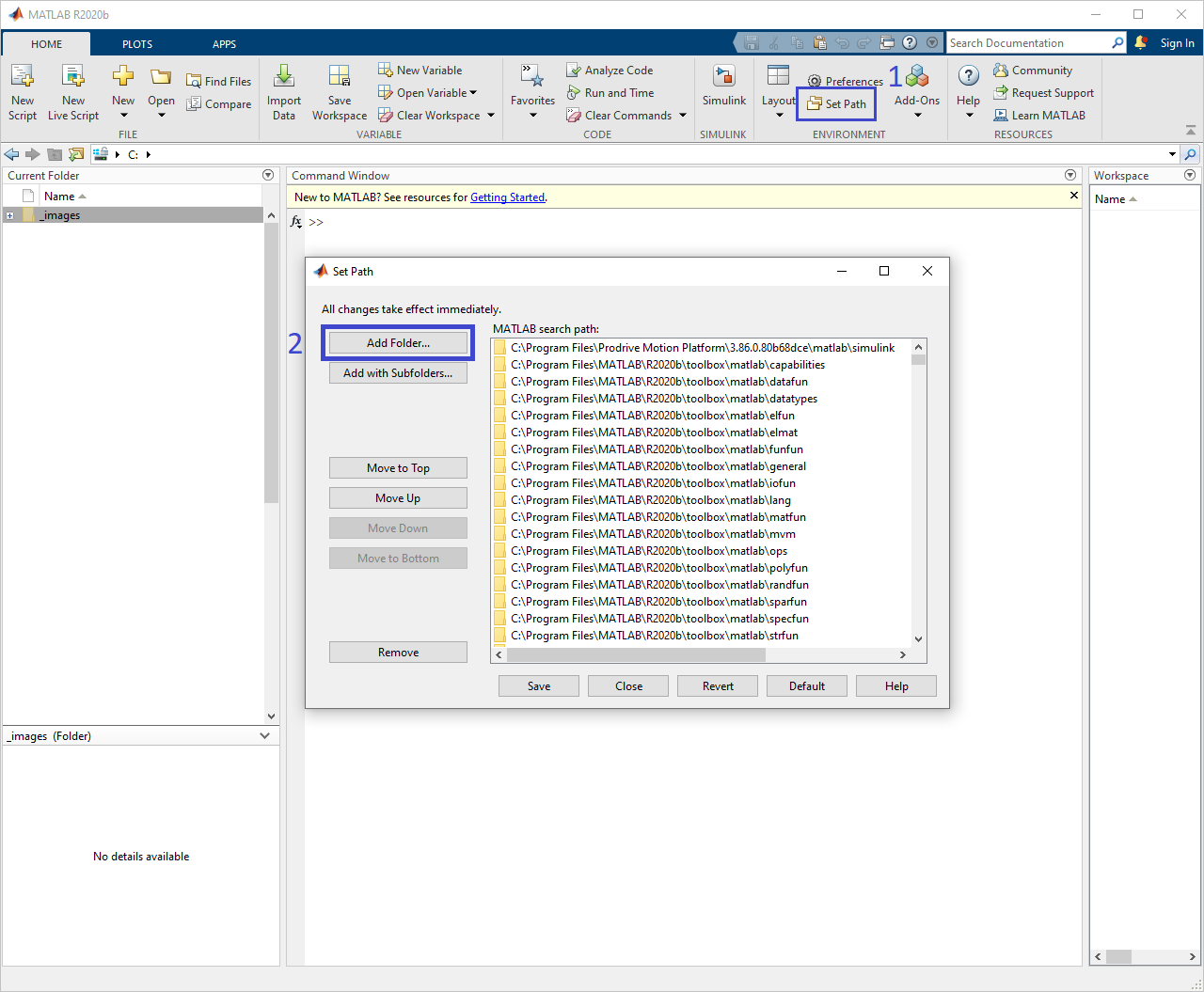
Add PMP Simulink folder to the MATLAB path
The PMP libraries are now added to the Simulink library and can be accessed as follows:
Open Simulink in the Home tab of the ribbon bar
Create a Blank Model.
Click on Library Browser to open all libraries.
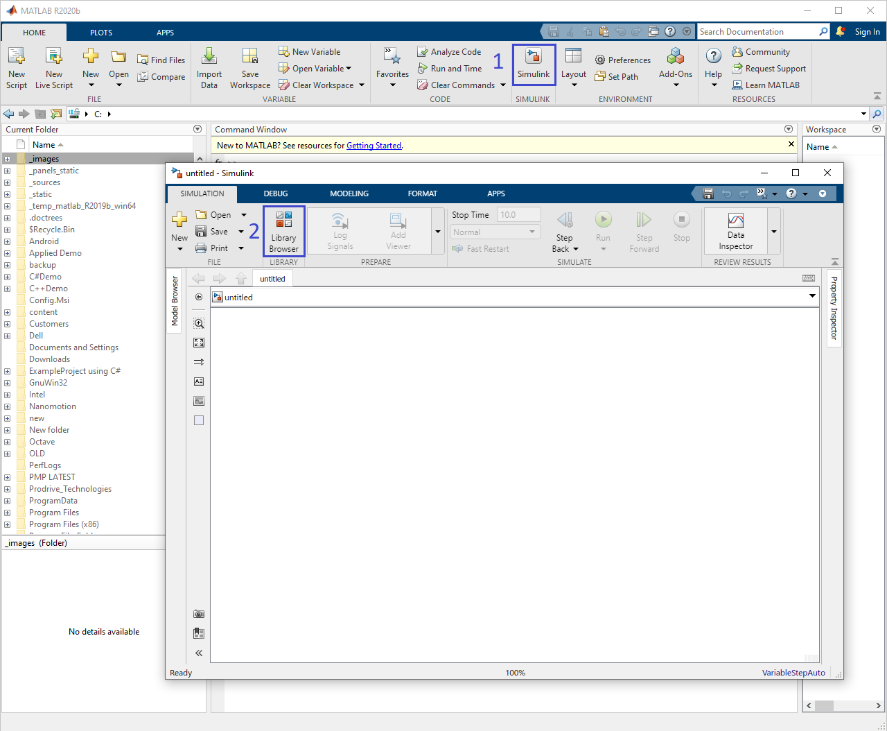
Open Simulink
If the Prodrive Motion Platform library is visible the PMP installation directory is correctly recognized by MATLAB.
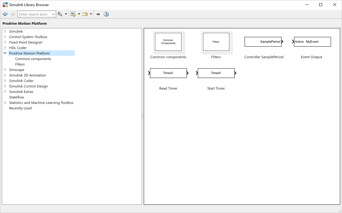
Prodrive Motion Platform library in the library browser
Simulink model
Create a Simulink model
As an example, we will create a feedforward block, which will be connected to a position feedback control. The block will take velocity and acceleration setpoint inputs from the trajectory interpolator and calculate the feedforward output.
The feedforward model is created in Simulink as follows:
Create Inport ports that will receive signals DemandVelocity and DemandAcceleration from the trajectory interpolator.
Create Gain blocks with variables: Kfv, Kfc and Kfa and add a Sign block for the Coulomb feedforward.
Create an Add block to sum all values.
Create an Outport port.
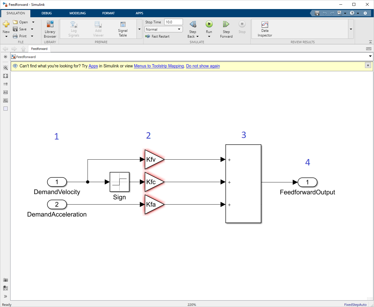
Feedforward model in Simulink
Note
The gain variables are marked in red since they have not been defined yet. The definition of variables is discussed later in Parameters.
Mapping to PMP objects
Inputs
During code generation, all Simulink inports are converted into PMP Input, i.e. the DemandVelocity and DemandAcceleration inports will become PMP inputs. Once the generated code is deployed, these inputs can be connected to signals within PMP. A bus or a vector inport will result in multiple PMP inputs since PMP inputs only support scalar values.
Parameters
By default, all Simulink block parameters are fixed during code generation and cannot be changed in PMP. To make parameters tunable in PMP, the parameter can be declared as PmpParameter object in Simulink.
The following MATLAB command should is used to create the PmpParameter Kfv:
Kfv = PmpParameter(min, max, resetValue, dataTypeStr, unit, description);
With the arguments:
Parameter |
Description |
|---|---|
min and max |
Used to limit what values are allowed to be configured. An empty argument can be inserted using |
resetValue |
The default value of the parameter. |
dataTypeStr |
Data-type of the parameter (string). Available type are: |
unit |
Unit of the parameter (string). Can be left empty using |
description |
Description of the parameter (string). Can be left empty using |
After code generation, a read/write PMP signal is generated that can be used to modify the value during execution.
Signals
Intermediate calculation results in the Simulink model are not visible in the PMP API unless they are marked as a test point. Test points defined in Simulink and outports will automatically appear as read-only signals in PMP and can be traced and monitored.
To create a test point:
Right-click on the route connected to the output of the Kfv gain block and select Properties.
Set the signal name to KfvOutput.
Check the Test point box.
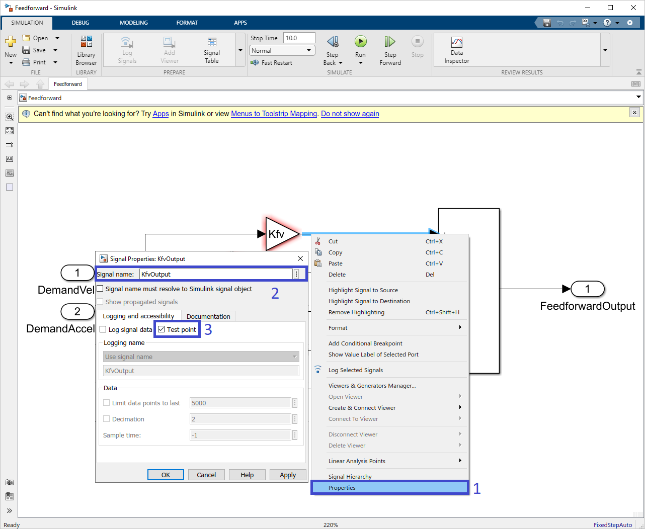
Create a Simulink test point
Repeat these steps for the routes connected to the outputs of the Kfc and Kfa gains blocks.
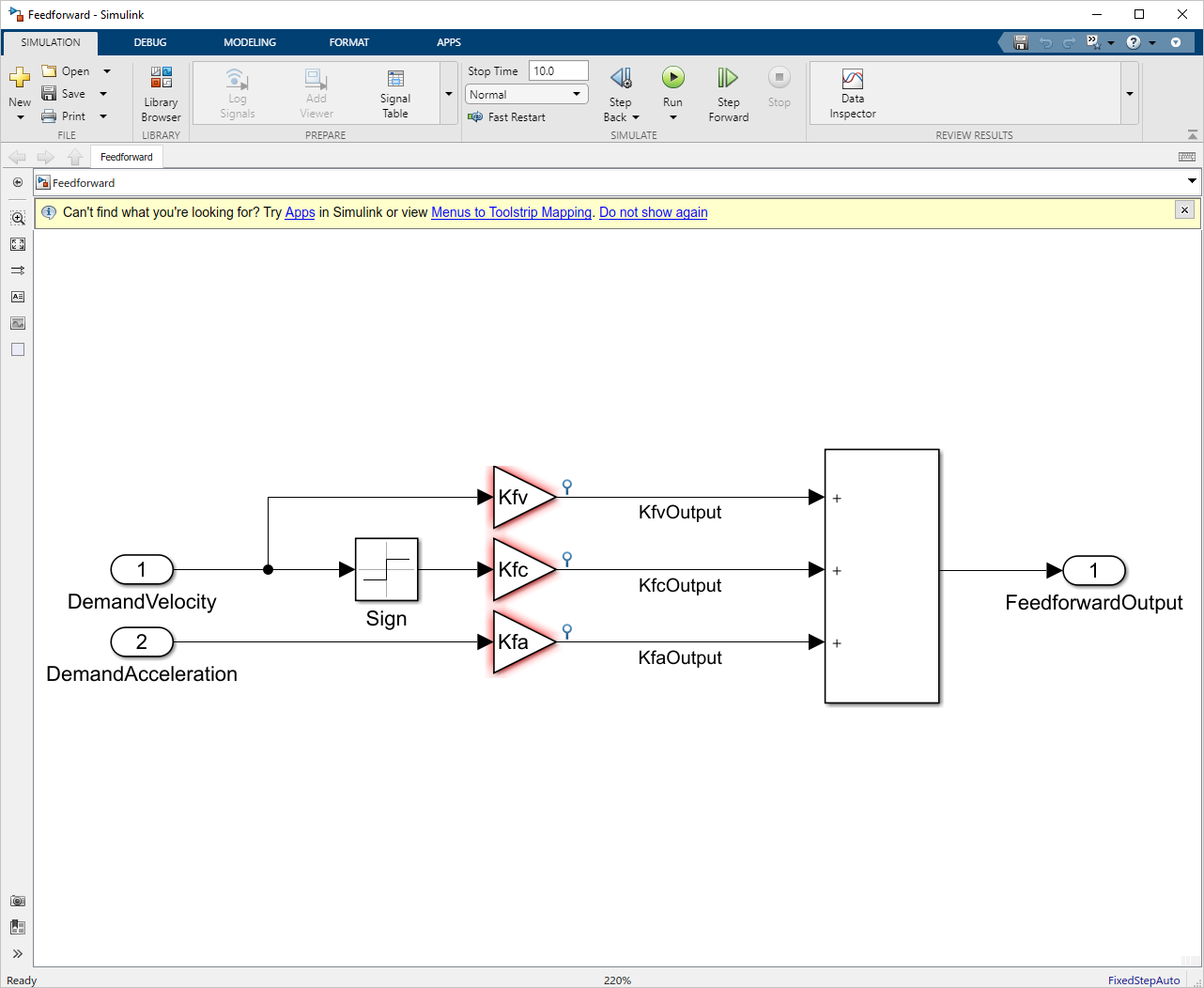
Simulink feedforward with all test points
By default, a PMP Signal is generated without metadata (min, max, unit, description). Optionally metadata can be added by specifying a PmpSignal variable in the workspace using the same name as the signal name of the test point or outport.
KfvOutput = PmpSignal(min, max, unit, description);
Where the arguments are:
Parameter |
Description |
|---|---|
min and max |
Used to limit what values are allowed to be configured. An empty argument can be inserted using |
unit |
Unit of the parameter (string). Can be left empty using |
description |
Description of the parameter (string). Can be left empty using |
The test point defined in the Simulink model with the name KfvOutput will now appear in PMP as signals with the description, min, max, and unit as specified. The data type of the signal is derived from the model.
Information overlays
Before proceeding, check the output data types and sample period of all blocks in the model.
Data types
It is important to consider the data types used throughout the model. For this example, we shall use the single type for all inports. The rest of the signals can remain on inherited (auto) and thus automatically defined by Simulink.
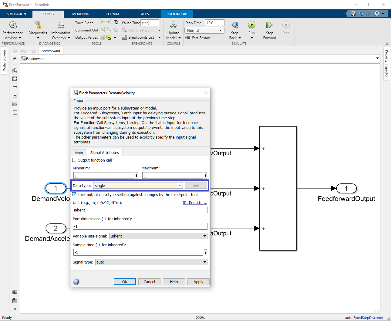
Set signal datatype to single
To verify that inheritance went as expected, the data type of each signal can be made visible via .
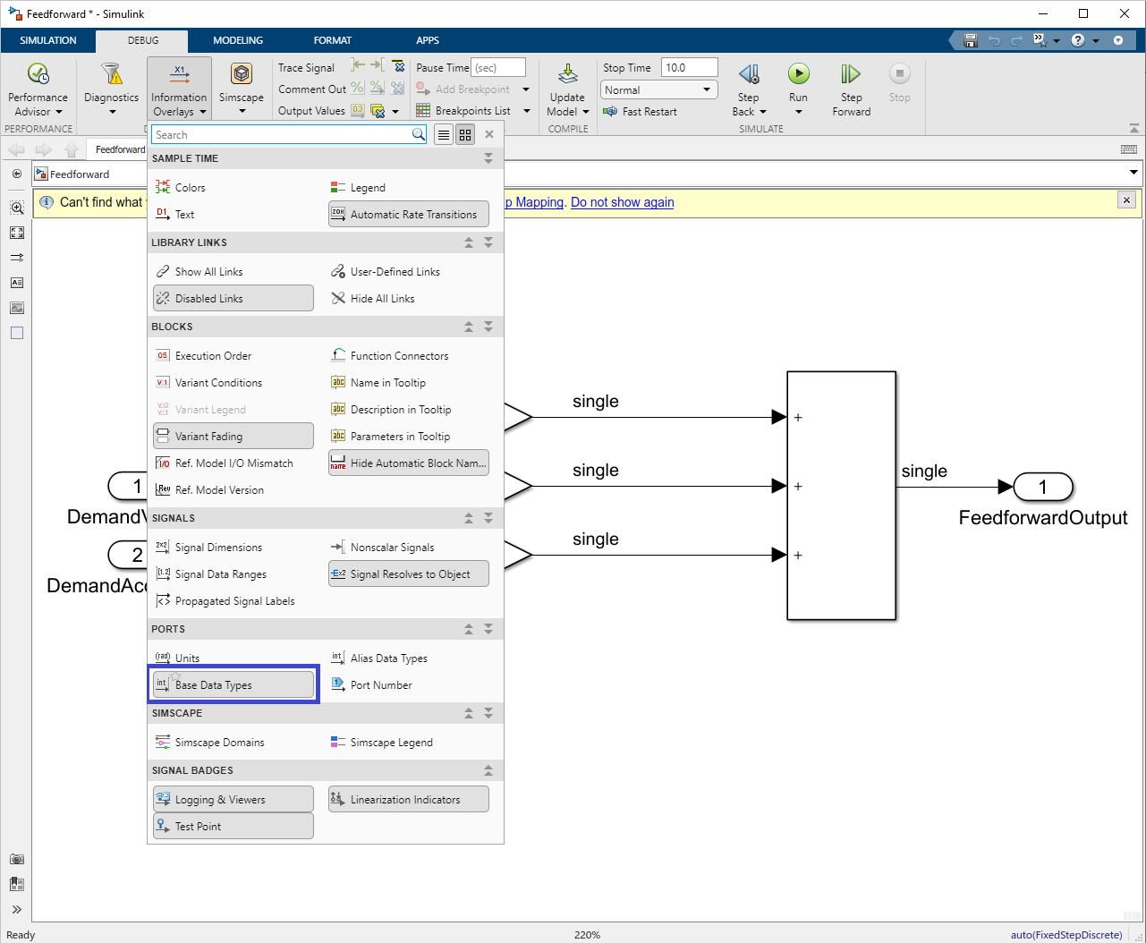
Feedforward model annotated with datatypes
Sample period
The sample period of the model is set during the code generation procedure, which will be discussed later in this guide. However, to verify that the sample periods are consistent throughout the model, a visual tool can be used.
First we need to define a fixed step solver as follows:
Click on .
In the solver selection, select Fixed-step.
In the solver details set the Fixed-step size (fundamental sample time) to 2kHz.
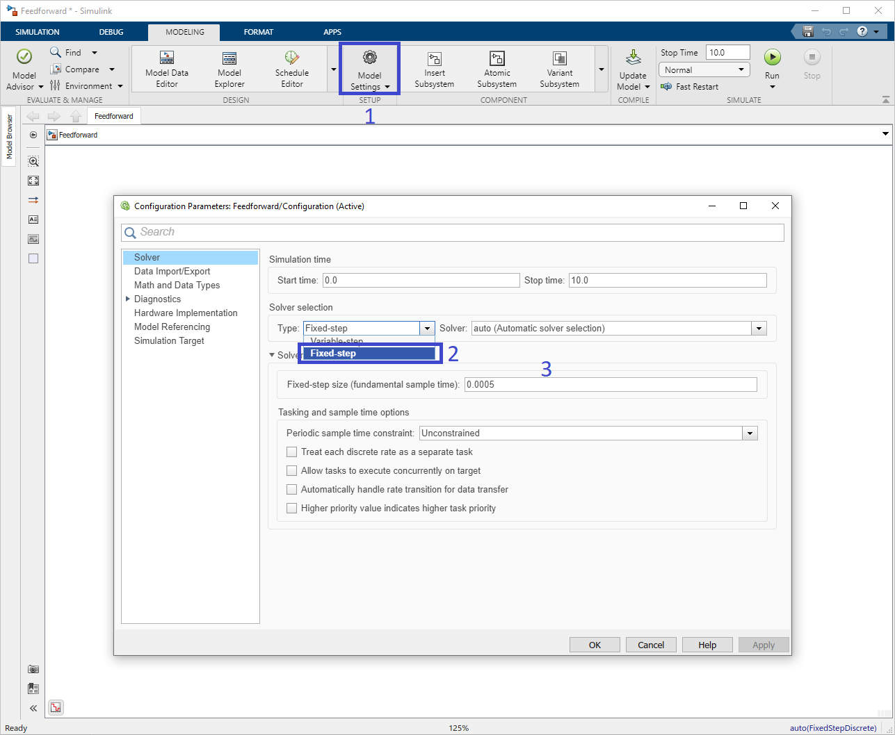
Set Simulink solver to fixed step.
By default, the sample time of all inputs, signals, and outputs inherit the sample time of the model.
To verify that inheritance went as expected, and that the sample time is uniform across all blocks, the sample time can be made visible via .
Note
Uniform color means uniform sampling time.
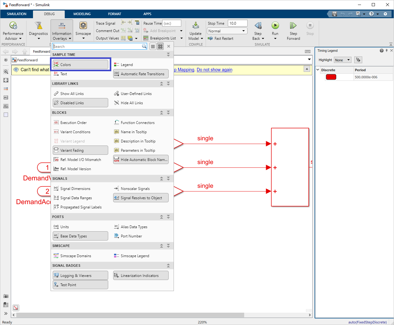
Feedforward model with visualized sample times
Compile model
Before generating a binary from the feedforward model, the model needs to be compiled first.
Save the model.
Load the following list of parameters and signals:
Kfc = PmpParameter([], [], 0.0, 'single', '', 'Coulomb friction compensation gain.');
Kfv = PmpParameter([], [], 0.0, 'single', '', 'Velocity compensation gain.');
Kfa = PmpParameter([], [], 0.0, 'single', '', 'Acceleration compensation gain.');

KfvOutput = PmpSignal([], [], '', 'Velocity compensation output.');
KfcOutput = PmpSignal([], [], '', 'Coulomb friction compensation output.');
KfaOutput = PmpSignal([], [], '', 'Acceleration compensation output.');
Note
As best practice, we recommend to put the above list in a configuration script, which is a available as
init.min the project files (see project download in Prerequisites).In Simulink, click on Run to compile the model.
The model is now ready to be converted into a binary file using the Code generation.
Code generation
The code generation generates a binary file that can be uploaded into PMP. Simulink code generation for PMP should be executed via MATLAB script.
The function PmpRunCodeGen() allows to set the configuration parameters and generate the code for PMP from an .m file or the command window.
The possible syntaxes for this function are:
PmpRunCodeGen(modelname,targetplatform,solver,sampleperiod)
PmpRunCodeGen(modelname,subsystemname,targetplatform,solver,sampleperiod)
PmpRunCodeGen(___,outputdir,binfilename)
Note
Code generation via the Simulink GUI is not advised nor documented, due to a large amount of required manual configurations.
Depending whether optional arguments are specified, the full model or only a specific subsystem can be built and the generated binary file can be renamed and moved to a user defined output directory.
Input |
Description |
|---|---|
modelname |
String containing the name of the simulink model. |
targetplatform |
|
solver |
|
sampleperiod |
Numeric or string containing the sample period used to generate code of the model.
If the model is not dependent on the sample period, then |
subsystemname |
(optional) string containing the name of the subsystem (if unique in the model) or full model path (in case it is not unique). |
outputdir |
(optional) string containing the user defined output directory for the binary file |
binfilename |
(optional) string specifying the user defined name of the binary file. |
enumeration('Pmp.TargetPlatform')
Enumerations feature auto-completion. I.e. when typing Pmp.TargetPlatform. and pressing the TAB key all options are displayed.
To generate code from our feedforward model, use the following command:
PmpRunCodeGen('Feedforward', PmpTargetPlatform.win_x86_64, PmpSolver.discrete, 'auto', 'CodeGenOutput', 'Feedforward');
Note
The above command uses the win_x86_64 target platform to be able to load the binary on a simulated system with the PMP simulator.
The Feedforward.bin binary file is generated in the output folder CodeGenOutput.
The output of the building process is displayed in the Command Window. If no errors occurred the message shall be as follows:
### Successful completion of build procedure for model: Feedforward
Model version <version> generated with code generation version <releaseID>(<releaseDate>).
The version is the Simulink model version, by default, this is incremented every time the model is saved (this can be changed via the Simulink model settings if desired). For traceability, the model version can be obtained via PMP after the binary files are uploaded into a PMP controller. The binary file can now be uploaded to a PMP controller.
Deployment
Update configuration file
Once the generated code binary is created, the file can be uploaded to the controller using a processing block template. A template defines an entity that can be created in PMP. A processing block template is a container for the generated code. From a template, one or more processing block instances can be created that execute the generated code and expose its interface.
This is done in the following steps:
Create a processing block template, and upload the generated library via the updatable of the template.
Create one (or more) processing block instances based on the template.
Connect inputs.
To configure the above steps, we use a configuration XML file.
Note
It is also possible to create a template, upload the generated processing block, and connect inputs via the API and the Tooling. However, we recommend using an XML configuration file, as it reduces API calls, allows quicker initialization of the system, and a quicker configuration of a controller.
We will reuse the configuration XML file from the Closed-loop system quick start guide, which already includes a simple position feedback control, and add our generated feedforward control.
Create a new template with the type ProcessingBlock:
 1
 2
 3
 4
 5
 6
 7
 8
 9
10
11
12
13
14
15
16
17
18
19
20
21
22
23
24
25
26
27
28
29
30
31
32
33
34
35
36
37
38
39
40
41
42
43
44
45
46
47
48
49
50
51
52
53
54
55
56
57
58
59
60
61
62
63
64
65
66
67
68
69
70
71
72
73
74
75
76
77
78
79
80
81
82
<Controller Name="Arcas 5EG-1">
  <!-- Template to create a simple position feedback controller -->
  <Template Name="PositionControlTemplate" TemplateType="ProcessingBlock">
    <Updatable Name="Updatable">
      <FilePath RelativeTo="File">PositionControlSimple-windows-x86_64.bin</FilePath>
    </Updatable>
  </Template>

  <Template Name="FeedforwardTemplate" TemplateType="ProcessingBlock">
    <Updatable Name="Updatable">
      <FilePath RelativeTo="File">../CodeGenOutput/Feedforward.bin</FilePath>
    </Updatable>
  </Template>

  <Template Name="PlantSecondOrderMechanicalTemplate" TemplateType="ProcessingBlock">
    <Updatable Name="Updatable">
      <FilePath RelativeTo="File">PlantSecondOrderMechanical-windows-x86_64.bin</FilePath>
    </Updatable>
  </Template>

  <!-- Axis control configuration -->
  <AxisControl Name="AxisX" Template="LogicalAxisControlStandard3rdOrderTemplate">

    <!-- Instantiate PlantSecondOrderMechanicalTemplate under AxisX -->
    <ProcessingBlock Name="Plant" Template="PlantSecondOrderMechanicalTemplate" CalculationStart="True">
      <Input Name="Actuator" Source="AxisX/PositionControl/ControlOutput"/>
      <Input Name="SamplePeriod" Source="SamplePeriod"/>
      <!-- Mass with viscous friction -->
      <Signal Name="Mass"      Unit="kg"  >10</Signal>
      <Signal Name="Damping"   Unit="Ns/m">1</Signal>
      <Signal Name="Stiffness" Unit="N/m" >0</Signal>
    </ProcessingBlock>

    <TrajectoryGenerator>
      <!-- Limited by bearings, mechanics, back-emf -->
      <Signal Name="MaximumVelocity"       Unit="m/s"  >1</Signal>
      <!-- Limited by max current of drive or max force/torque of motors -->
      <Signal Name="MaximumAcceleration"   Unit="m/s^2">10</Signal>
      <!-- Limited by motor inductance, max voltage of drive and control bandwidth -->
      <Signal Name="MaximumJerk"           Unit="m/s^3">100</Signal>
    </TrajectoryGenerator>

    <TrajectoryInterpolator>
      <!-- The following tuning configuration was created for purposes of this demo only -->
      <Input Name="DemandPositionOffset" Source="AxisX/PositionControl/DemandPositionOffset"/>
    </TrajectoryInterpolator>

    <CommandQueue>
      <!--Position control ClosedLoop state -->
      <Input Name="IsClosedLoop" Source="AxisX/PositionControl/IsClosedLoop"/>
    </CommandQueue>

    <!-- Create PositionControl ProccesingBlock -->
    <ProcessingBlock Name="PositionControl" Template="PositionControlTemplate">
      <!-- High when axis control state machine requests transition to closed loop (see IsClosedLoop signal) -->
      <Input Name="CloseLoopRequest" Source="AxisX/CommandQueue/CloseLoopRequest"/>
      <!-- Position setpoint is connected to trajectory generator -->
      <Input Name="DemandPosition" Source="AxisX/TrajectoryInterpolator/DemandPosition"/>
      <!-- Position feedback from the plant is connected to position controller -->
      <Input Name="PositionSensor" Source="AxisX/Plant/Position"/>
      <!-- Feedforward output from the Feedforward model is connected to FeedforwardControl -->
      <Input Name="FeedforwardControl" Source="AxisX/FeedForward/FeedforwardOutput" />
      <Filter Name="PID_LowPass">
        <!-- PD controller - for the purposes of this demo only -->
        <Signal Name="DifferentiatorFrequency">0.1</Signal>
        <Signal Name="ProportionalGain"       >700</Signal>
        <Signal Name="LowPassDamping"         >0.707</Signal>
        <Signal Name="LowPassFrequency"       >1000</Signal>
      </Filter>
    </ProcessingBlock>

    <ProcessingBlock Name="FeedForward" Template="FeedforwardTemplate">
      <Input Name="DemandVelocity" Source="AxisX/TrajectoryInterpolator/DemandVelocity"/>
      <Input Name="DemandAcceleration" Source="AxisX/TrajectoryInterpolator/DemandAcceleration"/>
      <!-- Gains -->
      <Signal Name="Kfa">0.5</Signal>
      <Signal Name="Kfc">2</Signal>
      <Signal Name="Kfv">1.5</Signal>
    </ProcessingBlock>

  </AxisControl>
</Controller>
Connect signals to inputs as follows:

Feedforward model interconnections
 1
 2
 3
 4
 5
 6
 7
 8
 9
10
11
12
13
14
15
16
17
18
19
20
21
22
23
24
25
26
27
28
29
30
31
32
33
34
35
36
37
38
39
40
41
42
43
44
45
46
47
48
49
50
51
52
53
54
55
56
57
58
59
60
61
62
63
64
65
66
67
68
69
70
71
72
73
74
75
76
77
78
79
80
81
82
<Controller Name="Arcas 5EG-1">
  <!-- Template to create a simple position feedback controller -->
  <Template Name="PositionControlTemplate" TemplateType="ProcessingBlock">
    <Updatable Name="Updatable">
      <FilePath RelativeTo="File">PositionControlSimple-windows-x86_64.bin</FilePath>
    </Updatable>
  </Template>

  <Template Name="FeedforwardTemplate" TemplateType="ProcessingBlock">
    <Updatable Name="Updatable">
      <FilePath RelativeTo="File">../CodeGenOutput/Feedforward.bin</FilePath>
    </Updatable>
  </Template>

  <Template Name="PlantSecondOrderMechanicalTemplate" TemplateType="ProcessingBlock">
    <Updatable Name="Updatable">
      <FilePath RelativeTo="File">PlantSecondOrderMechanical-windows-x86_64.bin</FilePath>
    </Updatable>
  </Template>

  <!-- Axis control configuration -->
  <AxisControl Name="AxisX" Template="LogicalAxisControlStandard3rdOrderTemplate">

    <!-- Instantiate PlantSecondOrderMechanicalTemplate under AxisX -->
    <ProcessingBlock Name="Plant" Template="PlantSecondOrderMechanicalTemplate" CalculationStart="True">
      <Input Name="Actuator" Source="AxisX/PositionControl/ControlOutput"/>
      <Input Name="SamplePeriod" Source="SamplePeriod"/>
      <!-- Mass with viscous friction -->
      <Signal Name="Mass"      Unit="kg"  >10</Signal>
      <Signal Name="Damping"   Unit="Ns/m">1</Signal>
      <Signal Name="Stiffness" Unit="N/m" >0</Signal>
    </ProcessingBlock>

    <TrajectoryGenerator>
      <!-- Limited by bearings, mechanics, back-emf -->
      <Signal Name="MaximumVelocity"       Unit="m/s"  >1</Signal>
      <!-- Limited by max current of drive or max force/torque of motors -->
      <Signal Name="MaximumAcceleration"   Unit="m/s^2">10</Signal>
      <!-- Limited by motor inductance, max voltage of drive and control bandwidth -->
      <Signal Name="MaximumJerk"           Unit="m/s^3">100</Signal>
    </TrajectoryGenerator>

    <TrajectoryInterpolator>
      <!-- The following tuning configuration was created for purposes of this demo only -->
      <Input Name="DemandPositionOffset" Source="AxisX/PositionControl/DemandPositionOffset"/>
    </TrajectoryInterpolator>

    <CommandQueue>
      <!--Position control ClosedLoop state -->
      <Input Name="IsClosedLoop" Source="AxisX/PositionControl/IsClosedLoop"/>
    </CommandQueue>

    <!-- Create PositionControl ProccesingBlock -->
    <ProcessingBlock Name="PositionControl" Template="PositionControlTemplate">
      <!-- High when axis control state machine requests transition to closed loop (see IsClosedLoop signal) -->
      <Input Name="CloseLoopRequest" Source="AxisX/CommandQueue/CloseLoopRequest"/>
      <!-- Position setpoint is connected to trajectory generator -->
      <Input Name="DemandPosition" Source="AxisX/TrajectoryInterpolator/DemandPosition"/>
      <!-- Position feedback from the plant is connected to position controller -->
      <Input Name="PositionSensor" Source="AxisX/Plant/Position"/>
      <!-- Feedforward output from the Feedforward model is connected to FeedforwardControl -->
      <Input Name="FeedforwardControl" Source="AxisX/FeedForward/FeedforwardOutput" />
      <Filter Name="PID_LowPass">
        <!-- PD controller - for the purposes of this demo only -->
        <Signal Name="DifferentiatorFrequency">0.1</Signal>
        <Signal Name="ProportionalGain"       >700</Signal>
        <Signal Name="LowPassDamping"         >0.707</Signal>
        <Signal Name="LowPassFrequency"       >1000</Signal>
      </Filter>
    </ProcessingBlock>

    <ProcessingBlock Name="FeedForward" Template="FeedforwardTemplate">
      <Input Name="DemandVelocity" Source="AxisX/TrajectoryInterpolator/DemandVelocity"/>
      <Input Name="DemandAcceleration" Source="AxisX/TrajectoryInterpolator/DemandAcceleration"/>
      <!-- Gains -->
      <Signal Name="Kfa">0.5</Signal>
      <Signal Name="Kfc">2</Signal>
      <Signal Name="Kfv">1.5</Signal>
    </ProcessingBlock>

  </AxisControl>
</Controller>
Define the values for the Feedforward gains:
 1
 2
 3
 4
 5
 6
 7
 8
 9
10
11
12
13
14
15
16
17
18
19
20
21
22
23
24
25
26
27
28
29
30
31
32
33
34
35
36
37
38
39
40
41
42
43
44
45
46
47
48
49
50
51
52
53
54
55
56
57
58
59
60
61
62
63
64
65
66
67
68
69
70
71
72
73
74
75
76
77
78
79
80
81
82
<Controller Name="Arcas 5EG-1">
  <!-- Template to create a simple position feedback controller -->
  <Template Name="PositionControlTemplate" TemplateType="ProcessingBlock">
    <Updatable Name="Updatable">
      <FilePath RelativeTo="File">PositionControlSimple-windows-x86_64.bin</FilePath>
    </Updatable>
  </Template>

  <Template Name="FeedforwardTemplate" TemplateType="ProcessingBlock">
    <Updatable Name="Updatable">
      <FilePath RelativeTo="File">../CodeGenOutput/Feedforward.bin</FilePath>
    </Updatable>
  </Template>

  <Template Name="PlantSecondOrderMechanicalTemplate" TemplateType="ProcessingBlock">
    <Updatable Name="Updatable">
      <FilePath RelativeTo="File">PlantSecondOrderMechanical-windows-x86_64.bin</FilePath>
    </Updatable>
  </Template>

  <!-- Axis control configuration -->
  <AxisControl Name="AxisX" Template="LogicalAxisControlStandard3rdOrderTemplate">

    <!-- Instantiate PlantSecondOrderMechanicalTemplate under AxisX -->
    <ProcessingBlock Name="Plant" Template="PlantSecondOrderMechanicalTemplate" CalculationStart="True">
      <Input Name="Actuator" Source="AxisX/PositionControl/ControlOutput"/>
      <Input Name="SamplePeriod" Source="SamplePeriod"/>
      <!-- Mass with viscous friction -->
      <Signal Name="Mass"      Unit="kg"  >10</Signal>
      <Signal Name="Damping"   Unit="Ns/m">1</Signal>
      <Signal Name="Stiffness" Unit="N/m" >0</Signal>
    </ProcessingBlock>

    <TrajectoryGenerator>
      <!-- Limited by bearings, mechanics, back-emf -->
      <Signal Name="MaximumVelocity"       Unit="m/s"  >1</Signal>
      <!-- Limited by max current of drive or max force/torque of motors -->
      <Signal Name="MaximumAcceleration"   Unit="m/s^2">10</Signal>
      <!-- Limited by motor inductance, max voltage of drive and control bandwidth -->
      <Signal Name="MaximumJerk"           Unit="m/s^3">100</Signal>
    </TrajectoryGenerator>

    <TrajectoryInterpolator>
      <!-- The following tuning configuration was created for purposes of this demo only -->
      <Input Name="DemandPositionOffset" Source="AxisX/PositionControl/DemandPositionOffset"/>
    </TrajectoryInterpolator>

    <CommandQueue>
      <!--Position control ClosedLoop state -->
      <Input Name="IsClosedLoop" Source="AxisX/PositionControl/IsClosedLoop"/>
    </CommandQueue>

    <!-- Create PositionControl ProccesingBlock -->
    <ProcessingBlock Name="PositionControl" Template="PositionControlTemplate">
      <!-- High when axis control state machine requests transition to closed loop (see IsClosedLoop signal) -->
      <Input Name="CloseLoopRequest" Source="AxisX/CommandQueue/CloseLoopRequest"/>
      <!-- Position setpoint is connected to trajectory generator -->
      <Input Name="DemandPosition" Source="AxisX/TrajectoryInterpolator/DemandPosition"/>
      <!-- Position feedback from the plant is connected to position controller -->
      <Input Name="PositionSensor" Source="AxisX/Plant/Position"/>
      <!-- Feedforward output from the Feedforward model is connected to FeedforwardControl -->
      <Input Name="FeedforwardControl" Source="AxisX/FeedForward/FeedforwardOutput" />
      <Filter Name="PID_LowPass">
        <!-- PD controller - for the purposes of this demo only -->
        <Signal Name="DifferentiatorFrequency">0.1</Signal>
        <Signal Name="ProportionalGain"       >700</Signal>
        <Signal Name="LowPassDamping"         >0.707</Signal>
        <Signal Name="LowPassFrequency"       >1000</Signal>
      </Filter>
    </ProcessingBlock>

    <ProcessingBlock Name="FeedForward" Template="FeedforwardTemplate">
      <Input Name="DemandVelocity" Source="AxisX/TrajectoryInterpolator/DemandVelocity"/>
      <Input Name="DemandAcceleration" Source="AxisX/TrajectoryInterpolator/DemandAcceleration"/>
      <!-- Gains -->
      <Signal Name="Kfa">0.5</Signal>
      <Signal Name="Kfc">2</Signal>
      <Signal Name="Kfv">1.5</Signal>
    </ProcessingBlock>

  </AxisControl>
</Controller>
Load the configuration file
In this guide the loading and verification steps are done using the PMP Tooling, alternatively this can be done using the API as described in the Closed-loop system quick start guide.
Right-click on the top-controller and select Load configuration from files.
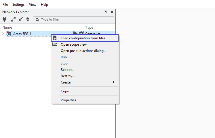
Upload configuration XML file
Verification
After the models are deployed on the controller, all PMP objects with corresponding attributes defined in the Simulink model are present:
Inports as inputs.
Test points and Outports as read-only signals.
Parameters as read/write signals.
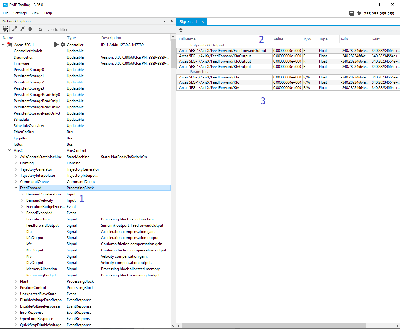
Feedforward model integration in PMP
Follow the Motion simulation chapter to create a Scope and execute a relative move command.
Note
Make sure to add the FeedforwardOutput signal to the scope.
Check the response of the Plant.
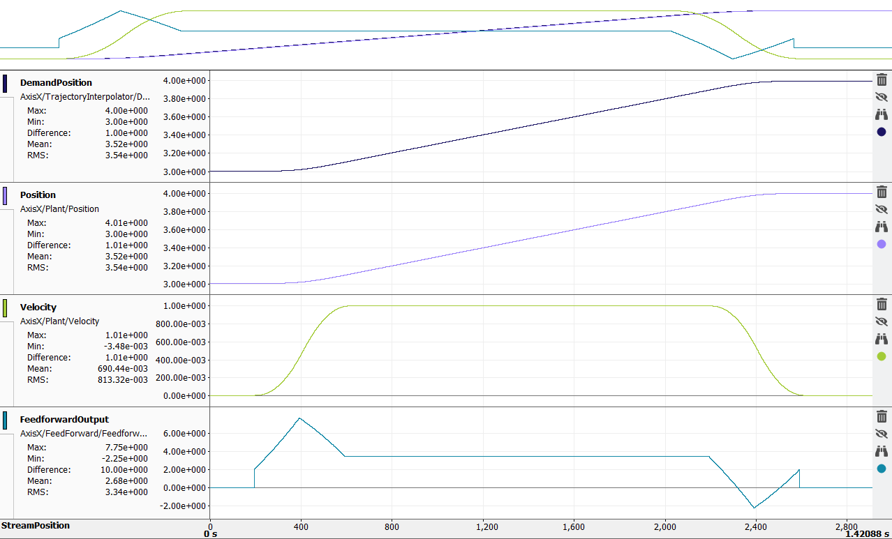
Closed loop system with Feedforward
See also
- Downloads
Prodrive Motion Platform (PMP) Download.
- Installation
Prodrive Motion Platform (PMP) installation guide.
- Tooling
Prodrive Motion Platform (PMP) Tooling GUI manual.
Limitations
The following limitiations hold when running generated code:
Generated code shall not (de)allocate memory in a dynamic way (i.e. while the controller is in Run state). An asynchronous exception will be generated in this case. Consider disabling the MATLABDynamicMemAlloc option to prevent dynamic memory allocations through a compilation error, as discussed in http://mathworks.com/help/simulink/gui/dynamicmemoryallocationinmatlabfunctions.html,