Closed-loop system
This guide provides step-by-step instructions on how to create a mechanical closed-loop system using the PMP Tooling and the PMP simulator. During this guide you will learn how to:
Create a position controller using a predefined template provided by PMP.
Create a second-order mechanical plant using a predefined template provided by PMP.
Interconnect all components to establish a closed-loop system.
Configure control parameters and limits.
Use a configuration XML file to upload pre-configured settings.
Use an axis command sequence to perform a relative move.
Configure a scope and trace the behavior of the simulated plant.
Introduction
In a mechanical closed-loop system, a feedback tracking device is used to transmit the output signal of a plant to a controller to account for expected errors. The controller evaluates the error between the setpoint command and the actual feedback of the plant and adjusts the system behavior accordingly. A typical mechanical closed-loop system can be described as follows:

Closed-loop system
In this guide a simulated mechanical plant model is used. Since we are using a simulated system, all of the required components can be created and controlled under a logical axis control provided by the Arcas 5EG top-controller.

Simulated closed-loop system
Top-controller - A top-level motion controller.
Axis control - A container for all functionality required to control an axis.
Setpoint - Position reference value, which is commanded by the user and calculated by the axis control trajectory interpolator.
Position controller - A position feedback controller, which automatically adjusts and reacts to the calculated error between the setpoint and the mechanical plant output.
Mechanical plant - Representation of the mechanical system, which includes an actuator and sensor model.
Prerequisites
Before continuing with the quick-start guide, please make sure that the following prerequisites are met:
PMP should be installed with Simulator and Tooling features. Follow the Installation quick-start guide if this is not yet the case.
A Typical installation includes the required Simulator and Tooling features.The closed-loop system quick start project files should be available. These files can be downloaded from Downloads.
- System description file:A system description file
system.xml, which describes the system properties and includes the controllers’ description. - Controller description file:A top-controller (Arcas)
controller_arcas_5eg.xml, which describes the controller’s main properties, such as templates, number of axes, processing blocks, updatables, and more.A sub-controller (Arcas FPGA)controller_arcas_5eg_slave, which includes digital IOs. - Configuration file:A configuration file
configuration.xml, which is used to configure a controller. - Position controller processing block binary:A simple position controller processing block binary
PositionControlSimple-windows-x86_64.bin, which is used to control the position set-points. - Mechanical plant processing block binary:A second order mechanical plant processing block binary
PlantSecondOrderMechanical-windows-x86_64.bin, which is used to simulate a mechanical plant.
Procedure
The guide will go through the followings steps to establish a closed-loop system:
Initialize system and discover top-controller.
Create components:
Axis control - Create an axis control from an predefined template.
Position controller - Create a position controller using a predefined template binary provided by PMP.
Mechanical plant - Create a second-order mechanical plant using a predefined template binary provided by PMP.
Component interconnections - Connecting signals to inputs.
Parameter configuration - Configure control parameters and limits.
Perform motion simulation - Command a relative move and trace the results using a scope.
Initialize system and discover top-controller
First, it is required to establish a connection with a top-controller. In this guide, the simulated system of the Create a simulator quick-start guide is used. If not already the case follow the Create a simulator quick-start guide to the point where the Arcas 5EG-1 is first started and in Config state.
Note
It is also possible to follow this quick-start guide on a physical Arcas 5EG controller.
As an additional prerequisite make sure the processing block binaries for the physical controller are available, i.e. PositionControlSimple-bb-armv8a_64.bin and PlantSecondOrderMechanical-bb-armv8a_64.bin
Create components
Axis control
Instantiate an axis control AxisX using the builtin LogicalAxisControlStandard3rdOrderTemplate template.
Expand the Arcas 5EG-1 tree (1).
Open the context menu of the LogicalAxisControlStandard3rdOrderTemplate template (2).
Select to open the Instantiate Axis control template dialog (3).
In the Instantiate Axis control template dialog (4):
Type the name AxisX.
Select the location Arcas 5EG-1.
Select Ok.
The instantiated AxisX will appear nested in the Arcas 5EG-1 top-controller (5).
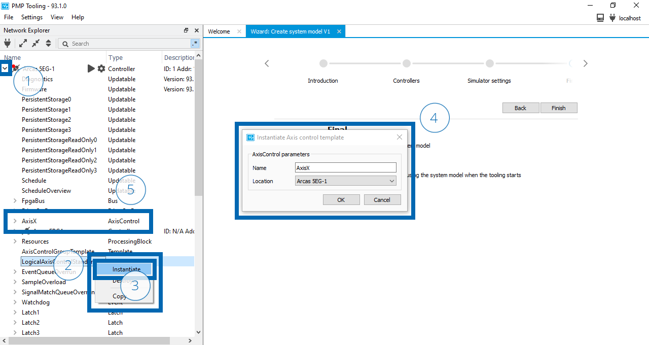
Instantiate axis control
Position control processing block
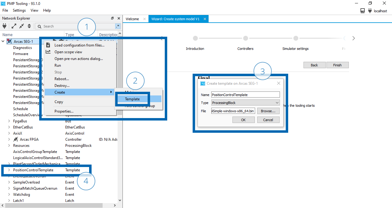
Instantiate a position control processing block PositionControl using the provided PositionControlSimple-windows-x86_64.bin.
Open the context menu of the Arcas 5EG-1 top-controller (1).
Select to open the Create template dialog (2).
In the Create template dialog (3):
Type the name PositionControlTemplate.
Select type ProcessingBlock.
Browse to and select the
PositionControlSimple-windows-x86_64.binfile.Select Ok.
The Updatable transactions dialog will appear and indicate the status of the upload of the
PositionControlSimple-windows-x86_64.binto the created PositionControlTemplate. Close the dialog if the upload is completed successful.The instantiated PositionControlTemplate will appear nested in the Arcas 5EG-1 top-controller (4).
Create position control template
Open the context menu of the created PositionControlTemplate template (1).
Select to open the Instantiate Processing block template dialog (2).
In the Instantiate Processing block template dialog (3):
Type the name PositionControl.
Select the location AxisX.
Select Ok.
The instantiated PositionControl will appear nested in the AxisX axis control (4).
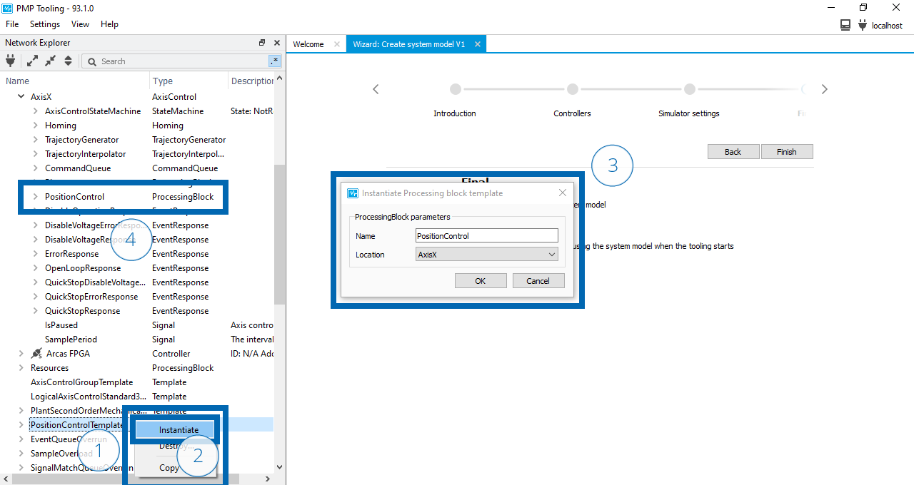
Instantiate position control processing block
See also
- PositionControlSimple
Technical reference for the position control simple processing block provided by PMP.
Mechanical plant processing block
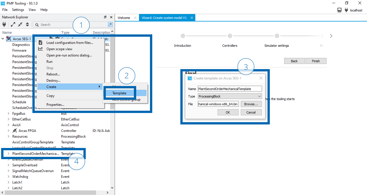
Instantiate a mechanical plant processing block Plant using the provided PlantSecondOrderMechanical-windows-x86_64.bin.
Open the context menu of the Arcas 5EG-1 top-controller (1).
Select to open the Create template dialog (2).
In the Create template dialog (3):
Type the name PlantSecondOrderMechanicalTemplate.
Select type ProcessingBlock.
Browse to and select the
PlantSecondOrderMechanical-windows-x86_64.binfile.Select Ok.
The Updatable transactions dialog will appear and indicate the status of the upload of the
PlantSecondOrderMechanical-windows-x86_64.binto the created PlantSecondOrderMechanicalTemplate. Close the dialog if the upload is completed successful.The instantiated PlantSecondOrderMechanicalTemplate will appear nested in the Arcas 5EG-1 top-controller (4).
Create plant template
Open the context menu of the created PlantSecondOrderMechanicalTemplate template (1).
Select to open the Instantiate Processing block template dialog (2).
In the Instantiate Processing block template dialog (3):
Type the name Plant.
Select the location AxisX.
Select Ok.
The instantiated Plant will appear nested in the AxisX axis control (4).
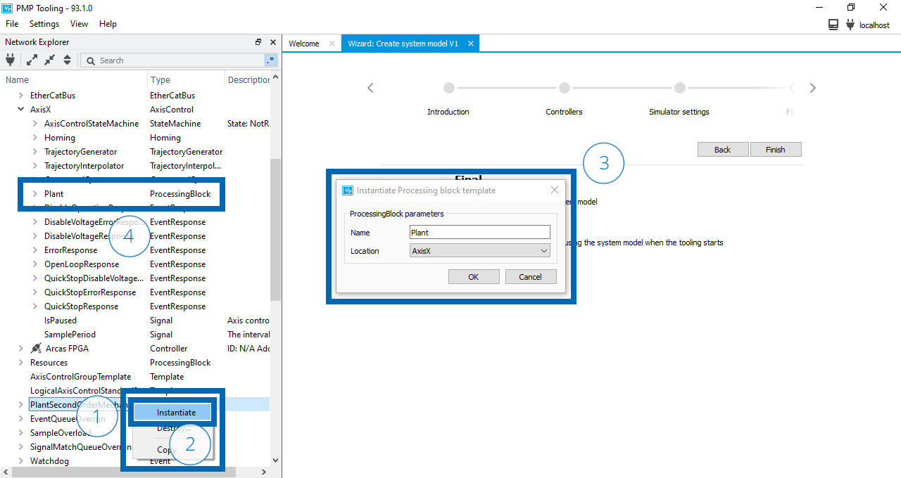
Instantiate plant processing block
See also
- PlantSecondOrderMechanical
Technical reference for the second order mechanical plant processing block provided by PMP.
Component interconnections
So far, we have instantiated an axis control, a mechanical plant, and a position control processing block. To create a closed-loop system, it is required to establish connections between the different axis control functionalities. The connections define the information exchange between the components. Based on the connections PMP can determine the order in which the components need to be calculated.
Component interconnections shows the required connections to form a minimal closed-loop system.
To establish a connection, each signal indicated with a ![]() needs to be connected to it’s corresponding input indicated with a
needs to be connected to it’s corresponding input indicated with a ![]() .
.

Component interconnections
To aid with creating the component interconnections first open a Signal view.
Open the View menu (1).
Select Signals to open a Signal view (2).
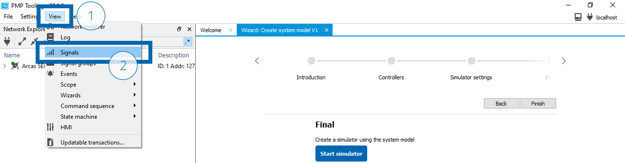
Open signal view
Position control & mechanical plant interconnections
Create the connections between PositionControl and Plant.
Find the Position signal in the Plant:
Type plant/position in the search box of the Network explorer (1).
Drag the signal to the Signal view (2).
Find the ControlOutput signal in the PositionControl:
Type positioncontrol/controloutput in the search box of the Network explorer (3).
Drag the signal to the Signal view (4).
Find the SamplePeriod signal in the Arcas 5EG-1:
Type sampleperiod in the search box of the Network explorer (5).
Drag the signal to the Signal view (6).
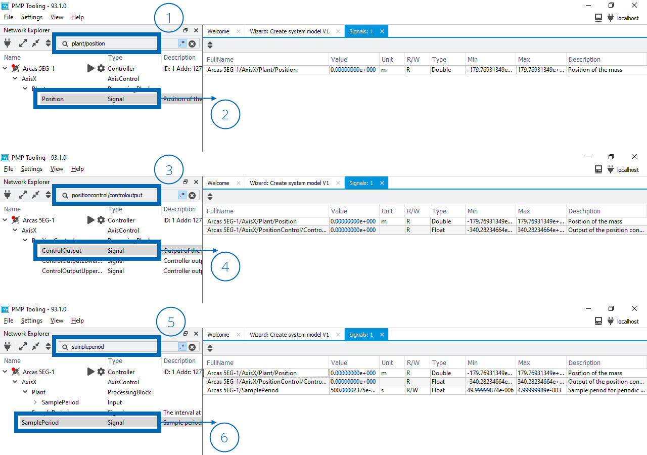
Drag and drop PositionControl and Plant signals in the signal view
Connect the PositionSensor input in the PositionControl:
Type positioncontrol/positionsensor in the search box of the Network explorer (7).
Drag the Position signal on top of the input in the Network Explorer (8).
A signal reference will appear under the input when correctly connected (9).
Connect the Actuator input in the Plant:
Type plant/actuator in the search box of the Network explorer (10).
Drag the ControlOutput signal on top of the input in the Network Explorer (11).
A signal reference will appear under the input when correctly connected (12).
Connect the SamplePeriod input in the Plant:
Type plant/sampleperiod in the search box of the Network explorer (13).
Drag the SamplePeriod signal on top of the input in the Network Explorer (14).
A signal reference will appear under the input when correctly connected (15).
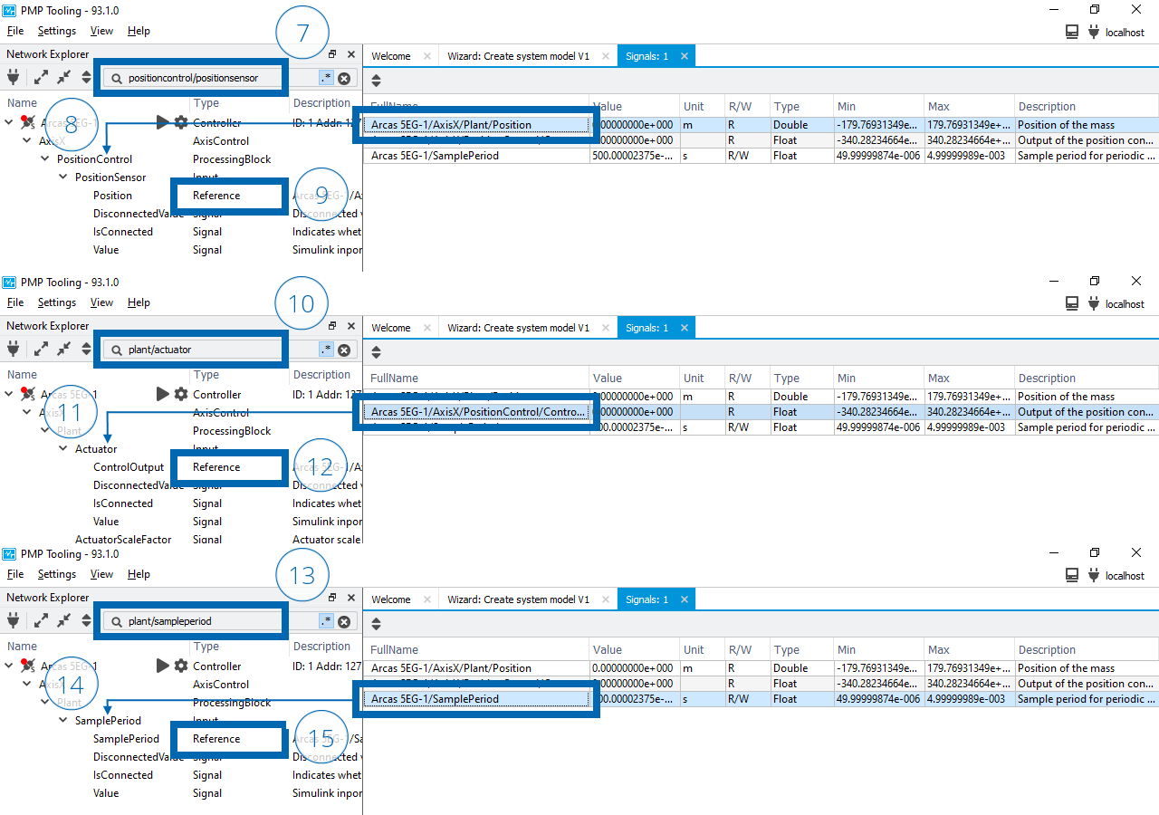
Connect PositionControl and Plant signals to their corresponding input
Calculation start
In Component interconnections it can be seen that a signal of PositionControl is connected to an input of Plant and a signal of Plant is connected to an input of PositionControl. These connections create a circular dependency. To indicate to PMP which processing block needs to be calculated first the Calculation start property of the Plant processing block needs to be enabled.
Open the context menu of the Plant processing block (1).
Select (2).
Enable the Calculation start property (3).
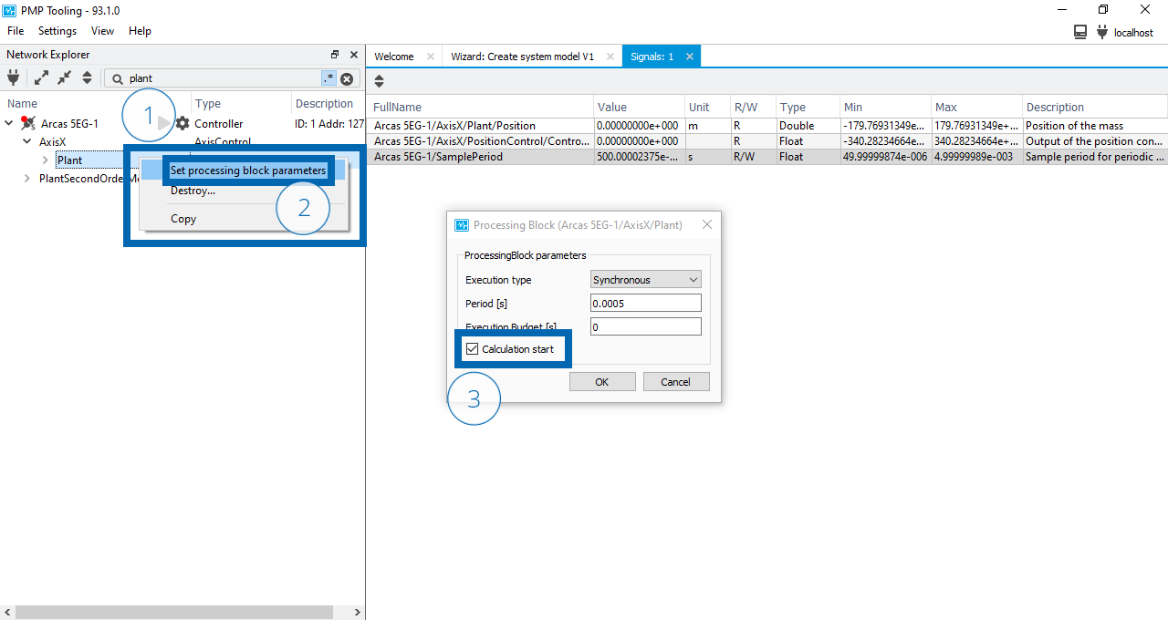
Set processing block CalculationStart on Plant processing block
Position control & trajectory interpolator interconnections
Create the connections between PositionControl and TrajectoryInterpolator.
Find the DemandPosition signal in the TrajectoryInterpolator:
Type trajectoryinterpolator/demandposition$ in the search box of the Network explorer (1).
Drag the signal to the Signal view (2).
Find the DemandPositionOffset signal in the PositionControl:
Type positioncontrol/demandpositionoffset in the search box of the Network explorer (3).
Drag the signal to the Signal view (4).
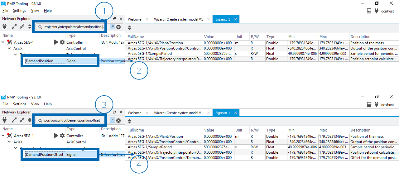
Drag and drop PositionControl and TrajectoryInterpolator signals in the signal view
Hint
The search box of the Network explorer supports regular expressions. For example, the $ at the end of trajectoryinterpolator/demandposition$ denotes end of string, so it matches DemandPosition but not DemandPositionHighLimit.
Connect the DemandPosition input in the PositionControl:
Type positioncontrol/demandposition in the search box of the Network explorer (5).
Drag the DemandPosition signal on top of the input in the Network Explorer (6).
A signal reference will appear under the input when correctly connected (7).
Connect the DemandPositionOffset input in the TrajectoryInterpolator:
Type trajectoryinterpolator/demandpositionoffset in the search box of the Network explorer (8).
Drag the DemandPositionOffset signal on top of the input in the Network Explorer (9).
A signal reference will appear under the input when correctly connected (10).
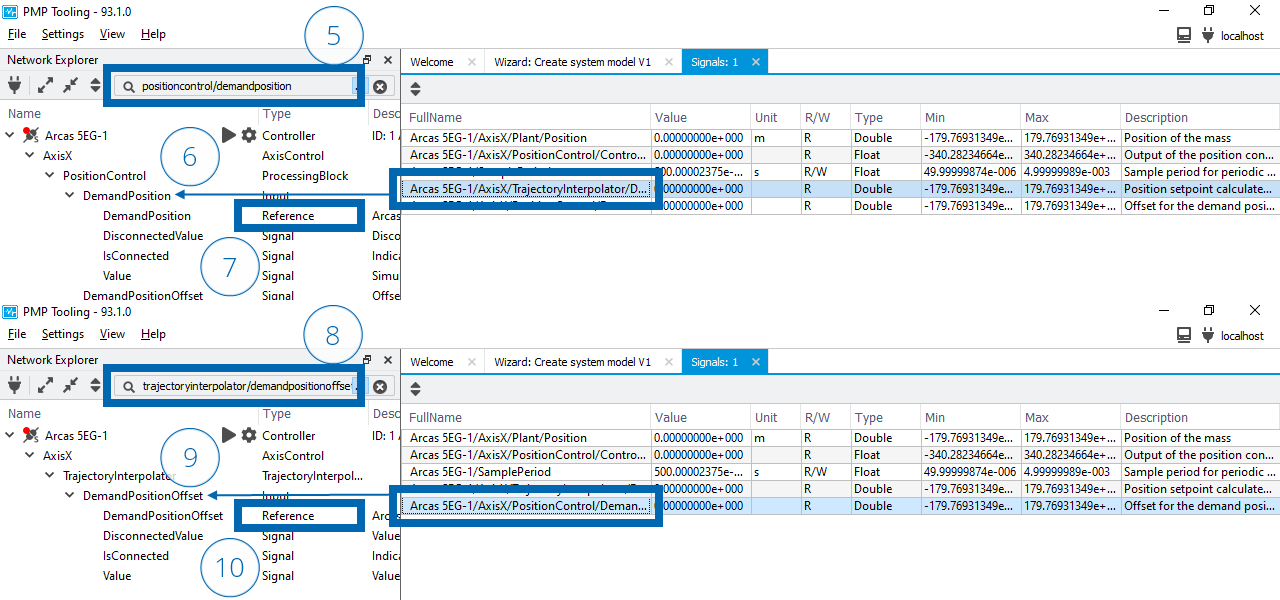
Connect PositionControl and TrajectoryInterpolator signals to their corresponding input
Note
It can be seen that TrajectoryInterpolator and PositionControl also have bi-directional interconnections and therefore a circular dependency. However, TrajectoryInterpolator is a special component which is always calculated first, so configuration of a Calculation start property is not needed.
Position control & command queue interconnections
Create the connections between PositionControl and CommandQueue.
Find the IsClosedLoop signal in the PositionControl:
Type positioncontrol/isclosedloop in the search box of the Network explorer (1).
Drag the signal to the Signal view (2).
Find the CloseLoopRequest signal in the CommandQueue:
Type commandqueue/closelooprequest in the search box of the Network explorer (3).
Drag the signal to the Signal view (4).
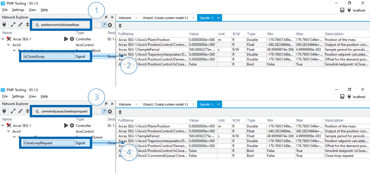
Drag and drop PositionControl and CommandQueue signals in the signal view
Connect the IsClosedLoop input in the CommandQueue:
Type commandqueue/isclosedloop in the search box of the Network explorer (5).
Drag the IsClosedLoop signal on top of the input in the Network Explorer (6).
A signal reference will appear under the input when correctly connected (7).
Connect the CloseLoopRequest input in the PositionControl:
Type positioncontrol/closelooprequest in the search box of the Network explorer (8).
Drag the CloseLoopRequest signal on top of the input in the Network Explorer (9).
A signal reference will appear under the input when correctly connected (10).
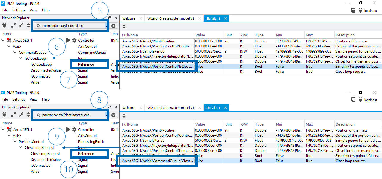
Connect PositionControl and CommandQueue signals to their corresponding input
Parameter configuration
The control parameters of the TrajectoryGenerator, PositionControl and Plant need to be configured to perform (simulated) closed loop motion. For this guide the position controller is configured as a PD controller and the plant as a mass with viscous friction.
Drag and drop the signals in Control parameters to the Signal view (1).
Configure the signal values in the Value column (2).
Signal |
Value |
|---|---|
AxisX/TrajectoryGenerator/MaximumVelocity |
1.0 |
AxisX/TrajectoryGenerator/MaximumAcceleration |
10.0 |
AxisX/TrajectoryGenerator/MaximumJerk |
100.0 |
AxisX/PositionControl/PID_LowPass/ProportionalGain |
700.0 |
AxisX/PositionControl/PID_LowPass/IntegratorFrequency |
0.0 |
AxisX/PositionControl/PID_LowPass/LowPassFrequency |
1000.0 |
AxisX/PositionControl/PID_LowPass/LowPassDamping |
0.707 |
AxisX/PositionControl/PID_LowPass/DifferentiatorFrequency |
0.1 |
AxisX/Plant/Mass |
10.0 |
AxisX/Plant/Damping |
1.0 |
AxisX/Plant/Stiffness |
0.0 |
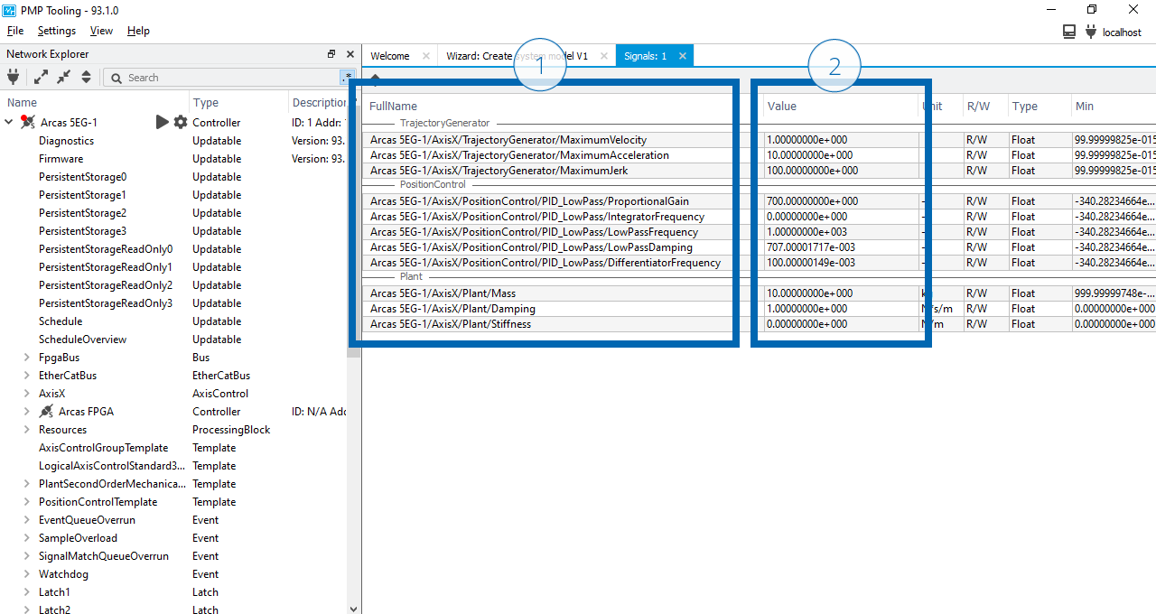
Parameter configuration in signal view
Note
When writing signal values to the controller, either via the PMP Tooling or directly via the API, the values are quantized to the datatype used by the controller. You can see this for example in the value of the PositionControl/PID_LowPass/LowPassDamping signal. The value \(0.707\) is written and the value \(0.70700001717\) is read, which is the closest IEEE-754 32-bit floating point representation of \(0.707\).
Hint
The Signal view supports separators to divide signals into groups to maintain a better overview. Open the context menu in the Signal view to add a separator. Double-click on the separator the change the name.
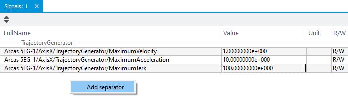
Add separators in the signal view to group signals
Upload configuration XML file
So far we have learned how to create and instantiate templates, interconnect the components and configure signals values using PMP Tooling. It is good to know how these configurations can be done via the PMP Tooling, however with a large set of configurations this can get tedious to always do manually. Typically these configurations should be stored in a configuration XML file.
Apply the same configuration using a configuration XML file.
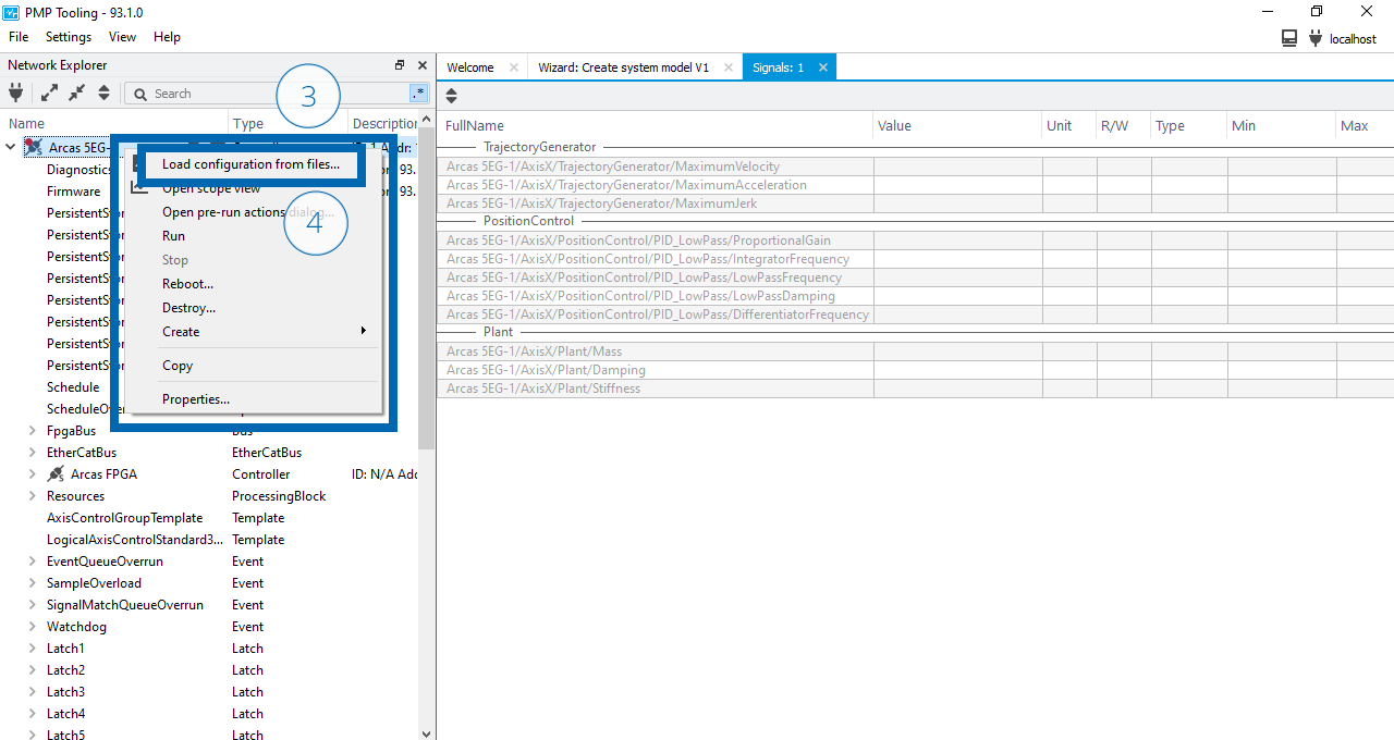
Reboot the Arcas 5EG-1 simulator to ensure a clean slate:
Open the context menu on the Arcas 5EG-1 (1).
Select (2).
Confirm the reboot request by clicking Ok.
Wait until the Arcas 5EG-1 is rebooted.
Apply the configuration XML file:
Open the context menu on the Arcas 5EG-1 (3).
Select (4).
Browse and open the
configuration.xmlfile.
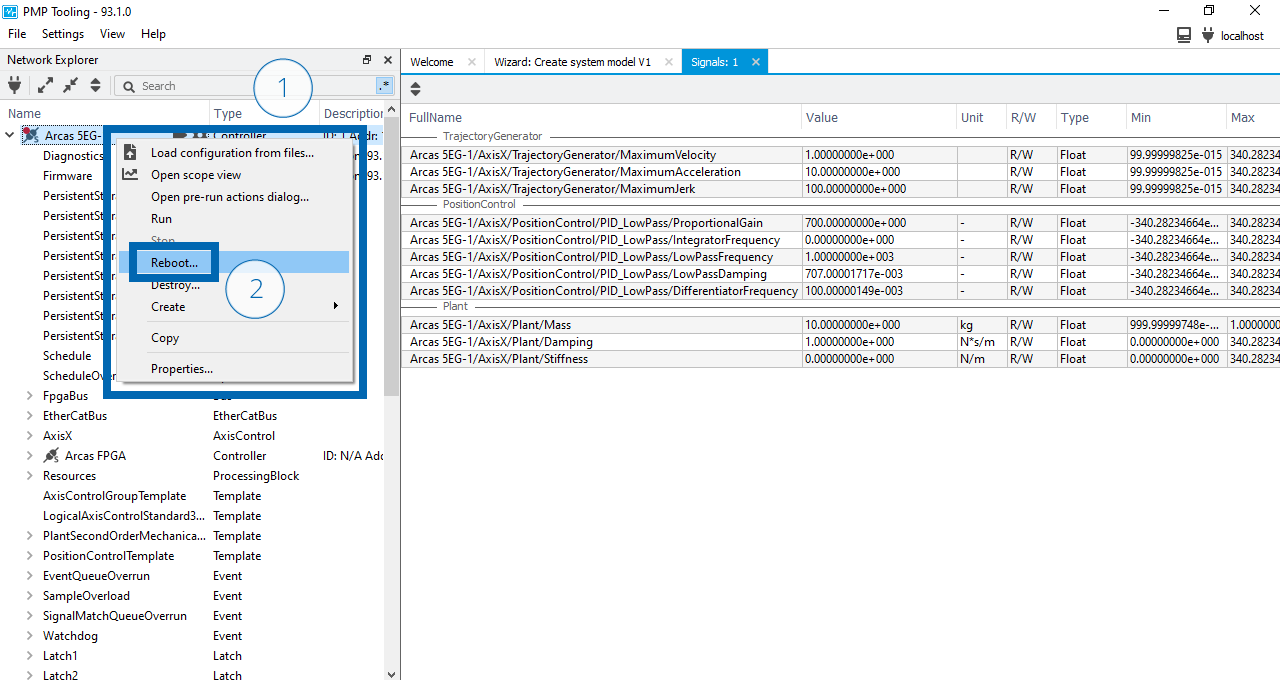
Reboot the Arcas 5EG-1 top-controller
Apply the configuration XML file to the Arcas 5EG-1 top-controller
Note
After the reboot request the signals in the Signal view grey out to indicate the signals are not available anymore. After the top-controller is rebooted the signals remain greyed out because AxisX, PositionControl and Plant are not recreated yet. After the configuration XML file is applied, the components are recreated, and the signals automatically reconnect.
Motion simulation
Now that our closed-loop system is fully defined, we can do movement with the simulated system.
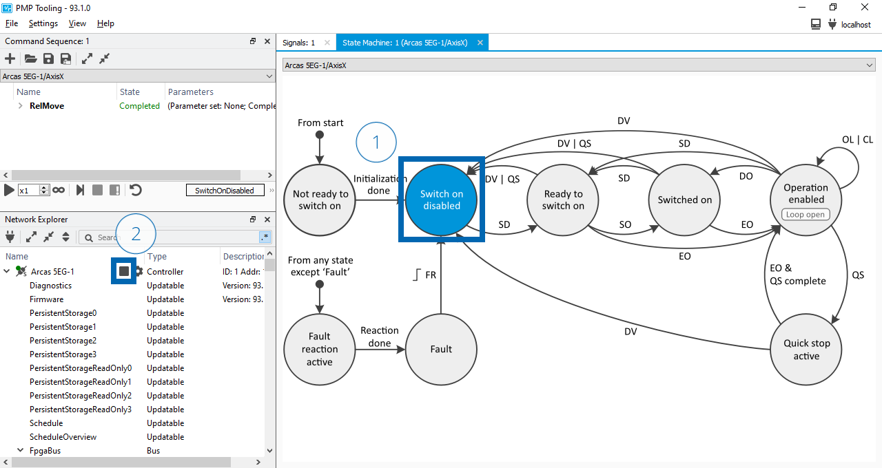
Enable top-controller and axis control
Move the Arcas 5EG-1 top-controller to the Run state and enable AxisX for closed-loop motion.
Click the
 button and wait until the indicator color is
  and the button changed to a
  button (1).
Open the context menu on AxisX (2).
Select (3).
Click on the Operation enabled state to enable the axis (4).
Click on CL to close the loop (5).
Verify that the loop status in the Operation enabled state indicates Loop closed.
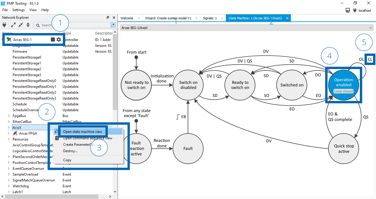
Enable top-controller and AxisX axis control
Command a move and configure acquisition
Configure a move command sequence, configure acquisition and move the axis.
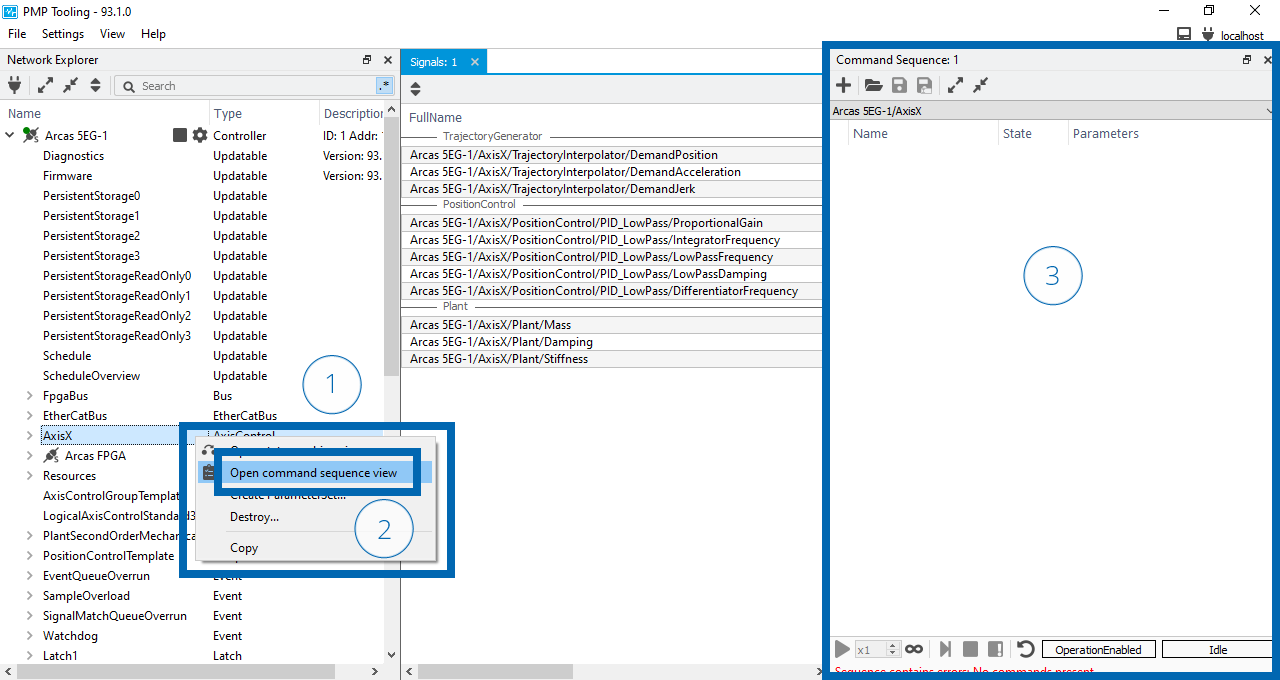
Open the context menu on AxisX (1).
Select (2).
A Command sequence view will appear on the right side of the screen (3).
Optionally move the Command sequence view above the Network explorer to create space on small screen resolutions:
Drag the Command sequence view using the title bar (4).
Drop the view above the Network explorer (5).
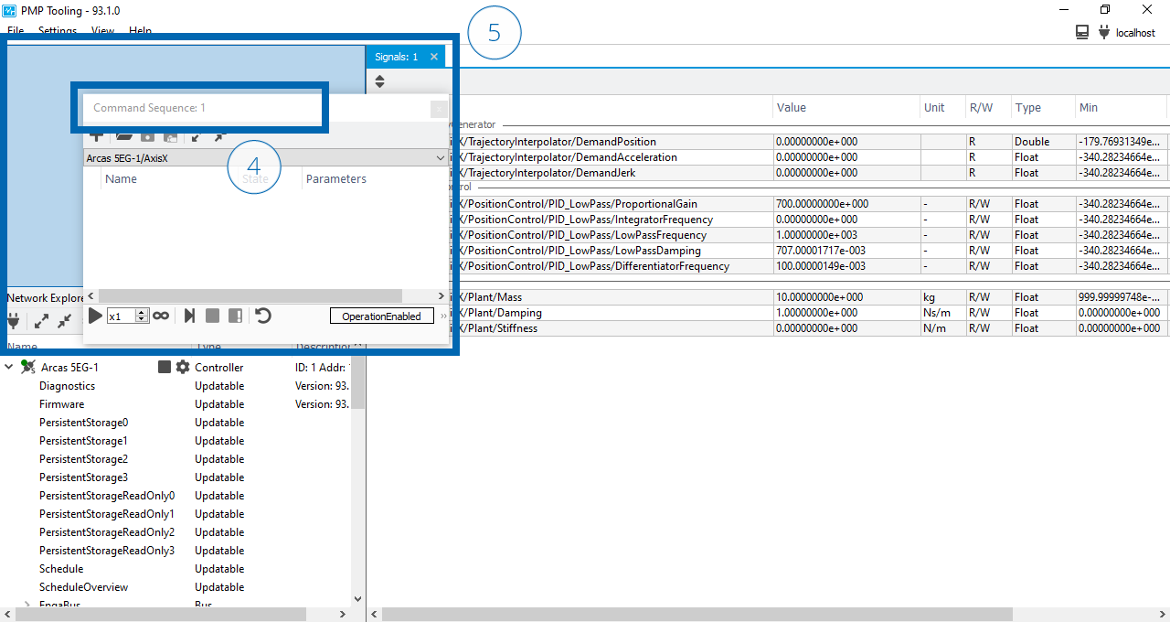
Open the context menu in the Command sequence view (6).
Select (7).
Set the Distance to \(1\) (8).
Open a axis control command sequence view
Dock the command sequence view above the network explorer
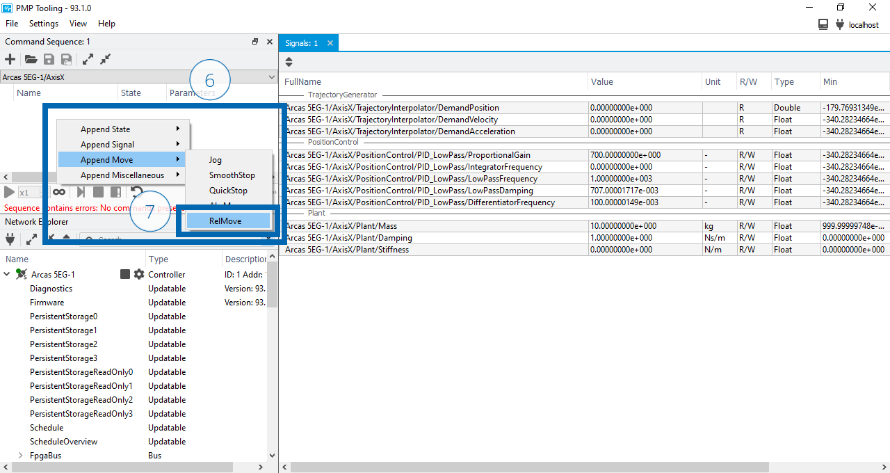
Add a RelMove in the command sequence view
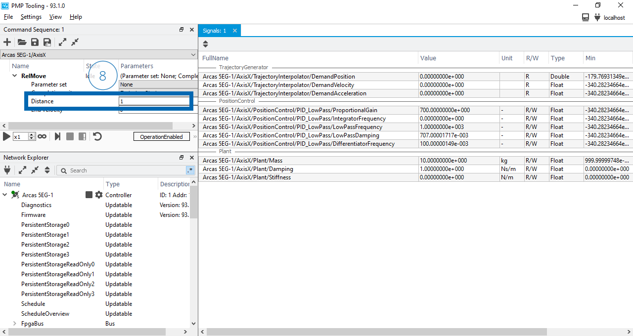
Configure the RelMove
Note
Motion profiles are defined by two sets of parameters:
Move constraints, such as maximum acceleration and velocity, are configured in the
configuration.xmlfile.Move end-conditions, such as distance for a relative move, are provided in the move command.
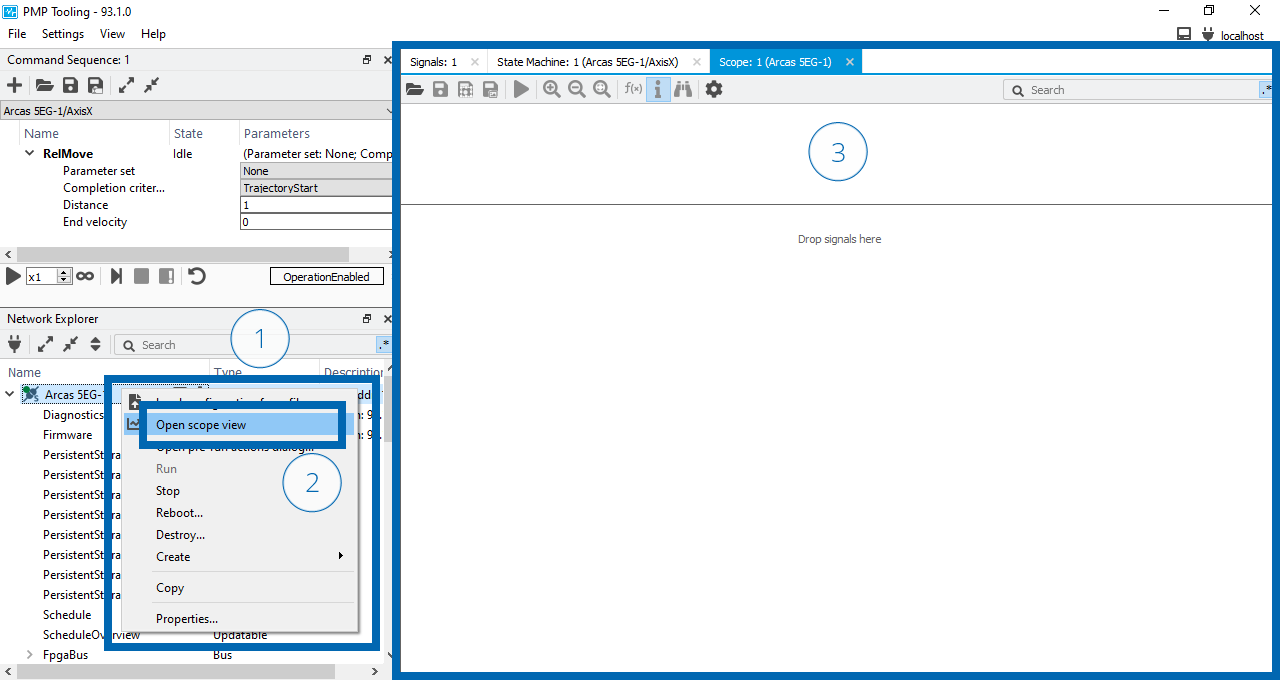
Configure a scope view for acquisition and move the axis with acquisition enabled:
Open the context menu on Arcas 5EG-1 (1).
Select (2).
A Scope view will appear on the right side of the screen (3).
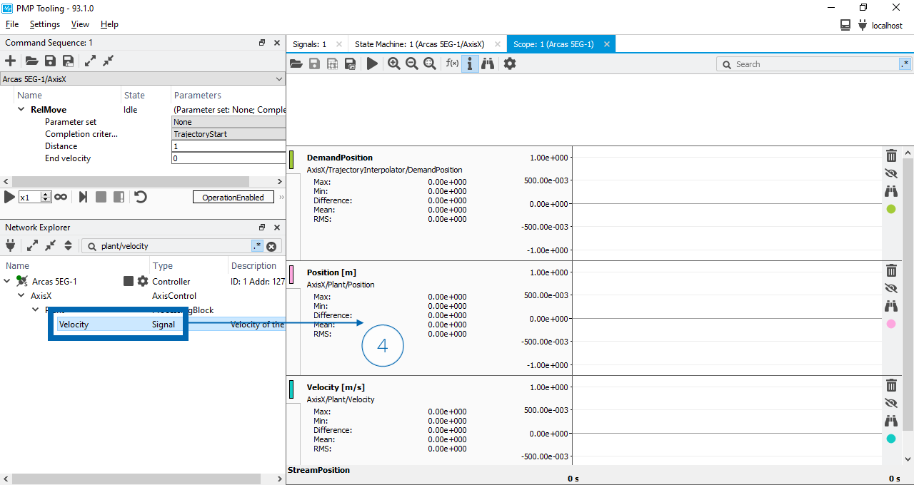
Drag and drop the signals in Acquisition signals to the Scope view (4).
Start acquisition using the
button in the Scope view (5).Start the move sequence using the
button in the Command sequence view (6).Stop acquisition using the
button in the Scope view (7).
Signal |
|---|
AxisX/TrajectoryInterpolator/DemandPosition |
AxisX/Plant/Position |
AxisX/Plant/Velocity |
Open a scope view
Add signals to the scope view
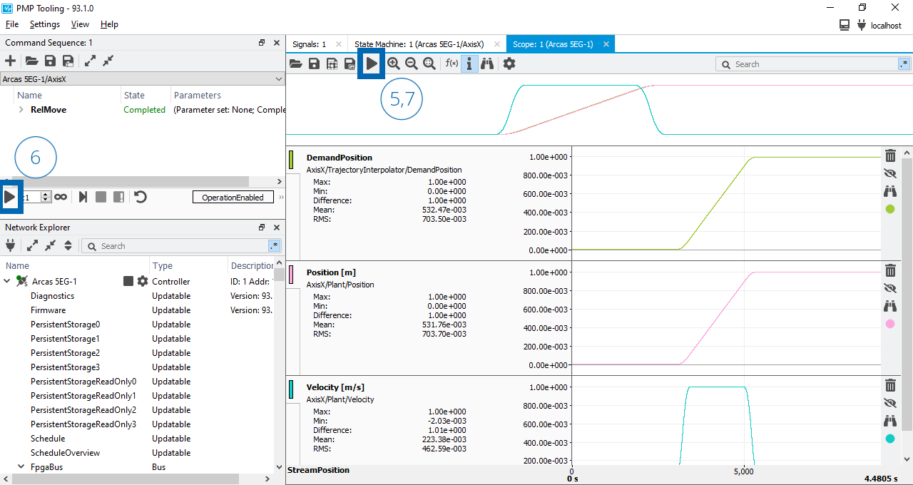
Move the axis with acquisition
The relative move sequence should look as follows:
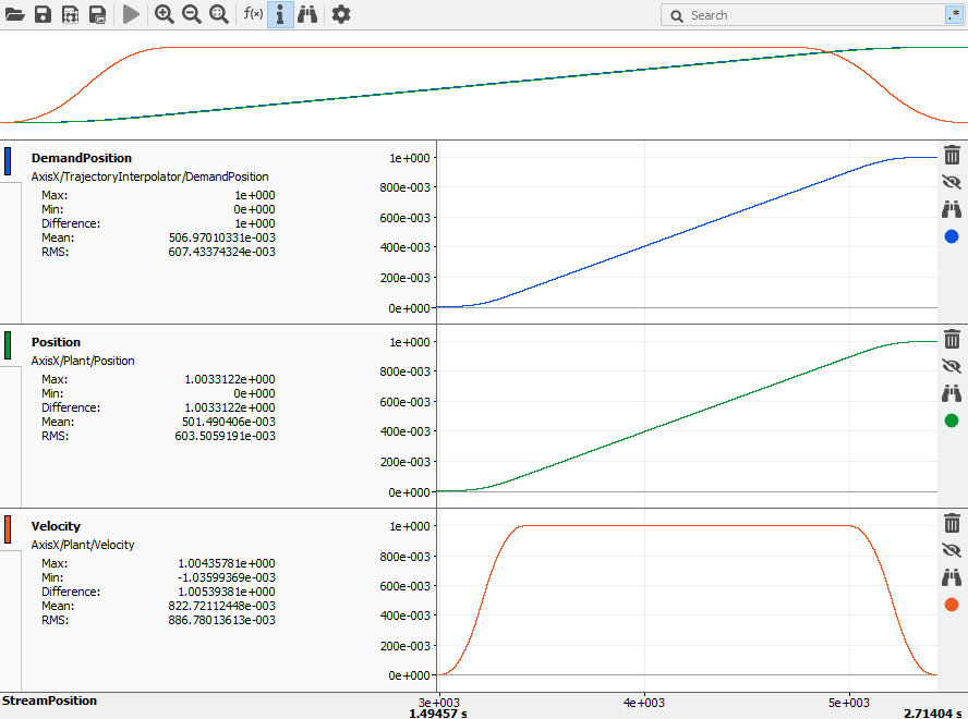
Simulated closed loop move sequence
Disable axis control
Disable the axis control and change the top-controller to Config state.
Click on the Switch on disabled state to enable the axis (1).
Click the
button (2).Wait until the indicator color is
 and the button changed to a button.
Disable the axis control and change the top-controller to Config state
Clean-up simulator
Now that the axis control is disabled we can clean-up the simulator.
Open the context menu of the Arcas 5EG-1 controller (1).
Select Destroy to destroy the simulator (2).
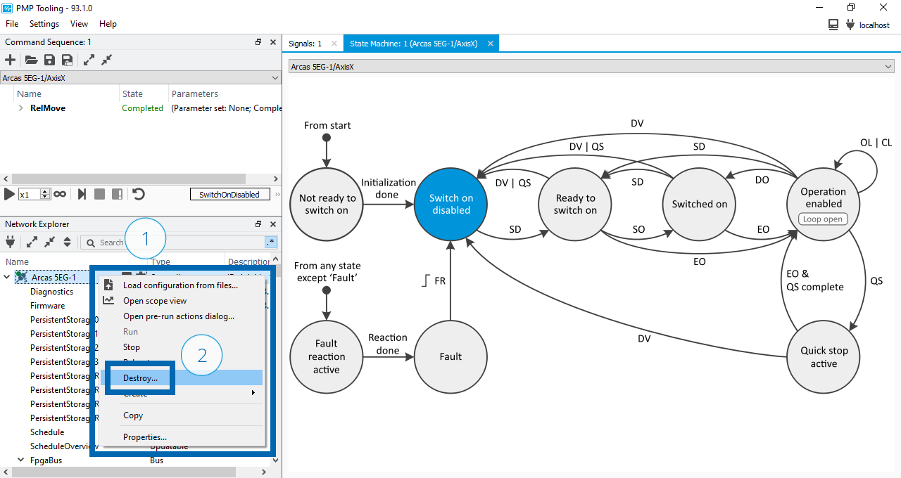
Clean-up simulator
Note
Closing the PMP Tooling does not destroy the simulator. The simulator keeps running until it is explicitly destroyed.
See also
- System description
For more information on system descriptions.
- Configuration
For more information on controller configuration.