Position based trigger
This guide provides step-by-step instructions on how to use a Position Based Trigger (PBT for short) using the API on actual hardware. During this guide you will learn how to:
Configure a Position Based Trigger module on a Cygnus D3.
Use a configuration XML file to upload pre-configured settings.
Measure the PBT trigger pulses on the Cygnus D3’s digital output using a hardware oscilloscope.
This chapter describes how to configure and work with a Position Based Trigger. The intended audience is any user that wants to use an available PBT module within a PMP (sub)controller that supports this. Some PMP knowledge is a prerequisite, and it is expected that the user has some experience with the PMP Tooling or API.
Introduction
The Position Based Trigger feature makes it possible to generate a pulse sequence based on selectable digital outputs with one of the selectable input positions. Typical use cases are applications for linescan cameras that are triggered on equidistant number of encoder counts along a motion profile.
Each PBT consists of the following five submodules:
Name |
Description |
|---|---|
Input Selector |
Selects one of the connected inputs to stream Position with same unit as the connected input (i.e. no scaling is performed). |
Position Extrapolator |
Extrapolates the selected Position to PositionExtrapolated with a 20MHz sample frequency for more fine-grained steps. This is mainly useful for absolute encoder protocols that are relatively slow (e.g. EnDAT, Hiperface, etc.). |
Position Comparator |
Generates a single PositionMatch pulse for every crossing between the PositionExtrapolated and user configurable compare position. |
Trigger Generator |
Generates a user configurable Trigger pulse sequence per incoming PositionMatch pulse. |
Output Selector |
Connects Trigger to one or multiple Output pins. Multiple PBTs can drive the same output as they are logically OR’d together. |
A diagram of the PBT, with its input and output connections as on the Cygnus D3 used in this guide, is shown below:

PBT overview for Cygnus D3
Prerequisites
Before continuing with the guide, please make sure that the following prerequisites are met:
PMP should be installed with at least the API feature. Follow the Installation quick-start guide if this is not yet the case.
A Typical installation includes the required API feature.The position-based-trigger guide project files should be available. These files can be downloaded from Downloads.
Note
The guide project files contains an example C++ project that can be built and executed in Microsoft Visual Studio using the provided .sln file. When executing the example project without using the .sln, ensure the working directory for the execution is the same as the directory that contains the .sln.
A hardware setup with a PC, Arcas, Cygnus D3 and oscilloscope. The Arcas and Cygnus D3 are used as reference throughout this example. The oscilloscope is for measuring the trigger pulses generated on the digital outputs of the Cygnus D3.
The resulting system in visualized in this image:

Hardware test setup system to verify Position Based Trigger operation
Attention
Various motors and encoders can be connected and configured on the Cygnus D3. The example configuration file in this guide assumes the position sensor is connected to the Enc1 connector of the Cygnus D3 and that sensor should be used as input for the PBTs. The configuration of the position sensor itself is beyond scope of this guide.
For movement the trajectory generator on the Arcas is used, it is assumed the axis control name is “Axis”.
Note
For more information and configuration related to axis control the Closed-loop system quick-start guide.
Procedure
The guide and example code project will go through the following examples:
Single PBT module
Multiple PBT modules
Special cases
Note
All of the above parameter configurations can be done using the API or Tooling. However, in this guide a configuration XML file is used to configure the different signals. This reduces API calls, allows quicker initialization, and is less error-prone.
All examples rely on two iterations of back and forth point-to-point movement of the axis and encoder between 0 and 70 millimeters. For each example the particular Variant of the config file is loaded at the start of the loop. This can be done with the following code example:
1 2 3 4 5 6 7 8 9 10 11 12 13 14 15 16 17 18 19 20 21 22 23 24 25 26 27 28 29 30 31 32 33 34 35 36 | auto moveSeq = commandQueue->CreateCommandSequence({
Pmp::ECommandType::AbsMove,
Pmp::ECommandType::AbsMove,
Pmp::ECommandType::AbsMove,
Pmp::ECommandType::AbsMove
});
const auto pointB = std::make_tuple(70.0, 0.0);
const auto pointA = std::make_tuple(0.0, 0.0);
auto commands = moveSeq->GetCommands();
for (auto i = 0; i < commands.size(); ++i)
{
auto move = std::dynamic_pointer_cast<Pmp::IAbsMove>(commands[i]);
move->SetConfiguration(i % 2 ? pointA : pointB);
move->SetCompletionCriterion(Pmp::ECommandCompletionCriterion::TrajectoryComplete);
}
// Loop over all example variants in the config file
std::vector<std::string> variants = {
"Interval",
"Array",
"IntervalBidirectional",
"TimeBased"
};
for (const auto& variant : variants)
{
// Setup Position Based Trigger parameters based on specific example
auto configurationFile = "../configuration-files/configuration.xml";
topController->LoadConfigurationFromFile(configurationFile, {{"Example", variant}});
// execute the movement sequence
commandQueue->Queue(moveSeq);
moveSeq->WaitComplete(10.0);
moveSeq->Reuse();
}
|
Examples
The following paragraphs explain each example in detail.
Interval mode
This example shows how to configure Interval mode. In Interval mode triggers are generated at equidistant intervals. After crossing the ArmPosition the comparator is armed, and a single PositionMatch pulse is generated starting at the crossing of PositionStart and repeated for each crossing of PositionStart shifted by PositionStep.
Once NumberOfPositionMatches PositionMatch pulses are generated the comparator automatically disarms itself and waits for the next ArmPosition crossing to (re)arm itself again.

Interval mode trigger generation
The following XML configuration sets up Interval mode on 1 PBT as described:
1 2 3 4 5 6 7 8 9 10 11 12 13 14 15 16 17 18 19 | <ProcessingBlock Name="PositionBasedTrigger1">
<Signal Name="Enable">0</Signal> <!-- ensure to disable PBT before writing all settings -->
<Signal Name="InputSelect">1</Signal> <!-- 1 = Enc1Position2, change if different encoder is used -->
<Signal Name="ExtrapolationSelect">2</Signal> <!-- 2 = Linear -->
<Signal Name="CompareSelect">1</Signal> <!-- 1 = Interval mode -->
<Signal Name="ArmPosition">500000</Signal> <!-- 5mm in encoder counts -->
<Signal Name="PositionStart">1000000</Signal> <!-- 10mm in encoder counts -->
<Signal Name="PositionStep">1000000</Signal> <!-- 10mm in encoder counts -->
<Signal Name="NumberOfPositionMatches">6</Signal>
<Signal Name="OutputSelectMask">0x1</Signal> <!-- 0x1 = RS485_TX_TOP -->
<Signal Name="DelayTime">0</Signal> <!-- 0 ns -->
<Signal Name="OnTime">2000000</Signal> <!-- 2 ms -->
<Signal Name="OffTime">0</Signal> <!-- 0 ns -->
<Signal Name="NumberOfTriggers">1</Signal>
<Signal Name="Enable">1</Signal> <!-- enabling PBT after writing all settings -->
</ProcessingBlock>
<ProcessingBlock Name="PositionBasedTrigger2">
<Signal Name="Enable">0</Signal>
</ProcessingBlock>
|
The highlighted lines are specific for Interval mode (e.g. the position comparator’s parameters). Running this example results in a scope plot as shown below.
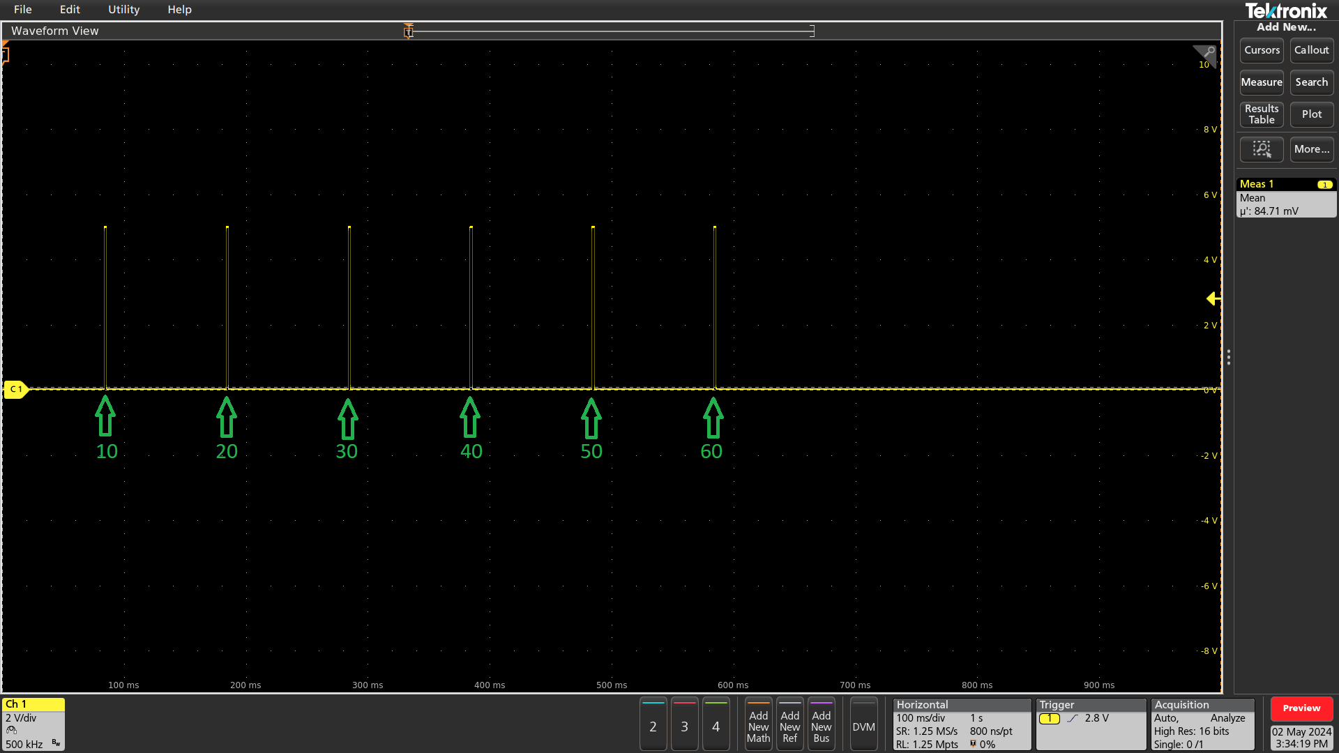
Interval mode trigger generation hw scope measurement
Array mode
This example shows how to configure Array mode. In Array mode PositionMatch are generated on crossings of position values provided by the PositionCompareArray binary updatable. After crossing the ArmPosition the comparator is armed, and a single PositionMatch pulse is generated starting at the crossing of first position in the array and repeated for each sequential position in the array.
Once all elements in the array are matched the comparator automatically disarms itself and waits for the next ArmPosition crossing to (re)arm itself again.

Array mode trigger generation
The following XML configuration sets up Array mode on 1 PBT as described:
1 2 3 4 5 6 7 8 9 10 11 12 13 14 15 16 17 18 19 | <ProcessingBlock Name="PositionBasedTrigger1">
<Signal Name="Enable">0</Signal> <!-- ensure to disable PBT before writing all settings -->
<Signal Name="InputSelect">1</Signal> <!-- 1 = Enc1Position2, change if different encoder is used -->
<Signal Name="ExtrapolationSelect">2</Signal> <!-- 2 = Linear -->
<Signal Name="CompareSelect">2</Signal> <!-- 2 = Array mode -->
<Signal Name="ArmPosition">500000</Signal> <!-- 5mm in encoder counts -->
<Updatable Name="PositionCompareArray">
<FilePath RelativeTo="File">PositionCompareArray.bin</FilePath>
</Updatable>
<Signal Name="DelayTime">0</Signal> <!-- 0 ns -->
<Signal Name="OnTime">2000000</Signal> <!-- 2 ms -->
<Signal Name="OffTime">0</Signal> <!-- 0 ns -->
<Signal Name="NumberOfTriggers">1</Signal>
<Signal Name="OutputSelectMask">0x1</Signal> <!-- 0x1 = RS485_TX_TOP -->
<Signal Name="Enable">1</Signal> <!-- enabling PBT after writing all settings -->
</ProcessingBlock>
<ProcessingBlock Name="PositionBasedTrigger2">
<Signal Name="Enable">0</Signal>
</ProcessingBlock>
|
The emphasized lines are specific for Array mode (e.g. the position comparator’s parameters).
Note
The PositionCompareArray.bin is applied, which contains an array of Integer64 values the comparator will use.
It can be created in different ways, for example using MATLAB or Python which are shown in the following code snippets.
1 2 3 4 5 6 7 8 9 | # PositionCompareArray binary generator
import numpy as np
position_array_si = np.array([10.0, 15.0, 35.0, 45.0, 50.0, 65.0]) # [mm]
encoder_factor = 1e-5 # [mm/EC]
position_array_ec = position_array_si / encoder_factor # [EC]
with open("PositionCompareArray.bin", "wb") as f:
position_array_ec.round().astype("int64").tofile(f)
|
1 2 3 4 5 6 7 8 | % PositionCompareArray binary generator
position_array_si = [10.0 15.0 35.0 45.0 50.0 65.0]; % [mm]
encoder_factor = 1e-5; % [mm/EC]
position_array_ec = position_array_si / encoder_factor; % [EC]
fid = fopen('PositionCompareArray.bin','w');
fwrite(fid,position_array_ec,'integer*8');
fclose(fid);
|
Running this example results in a scope plot as shown below.
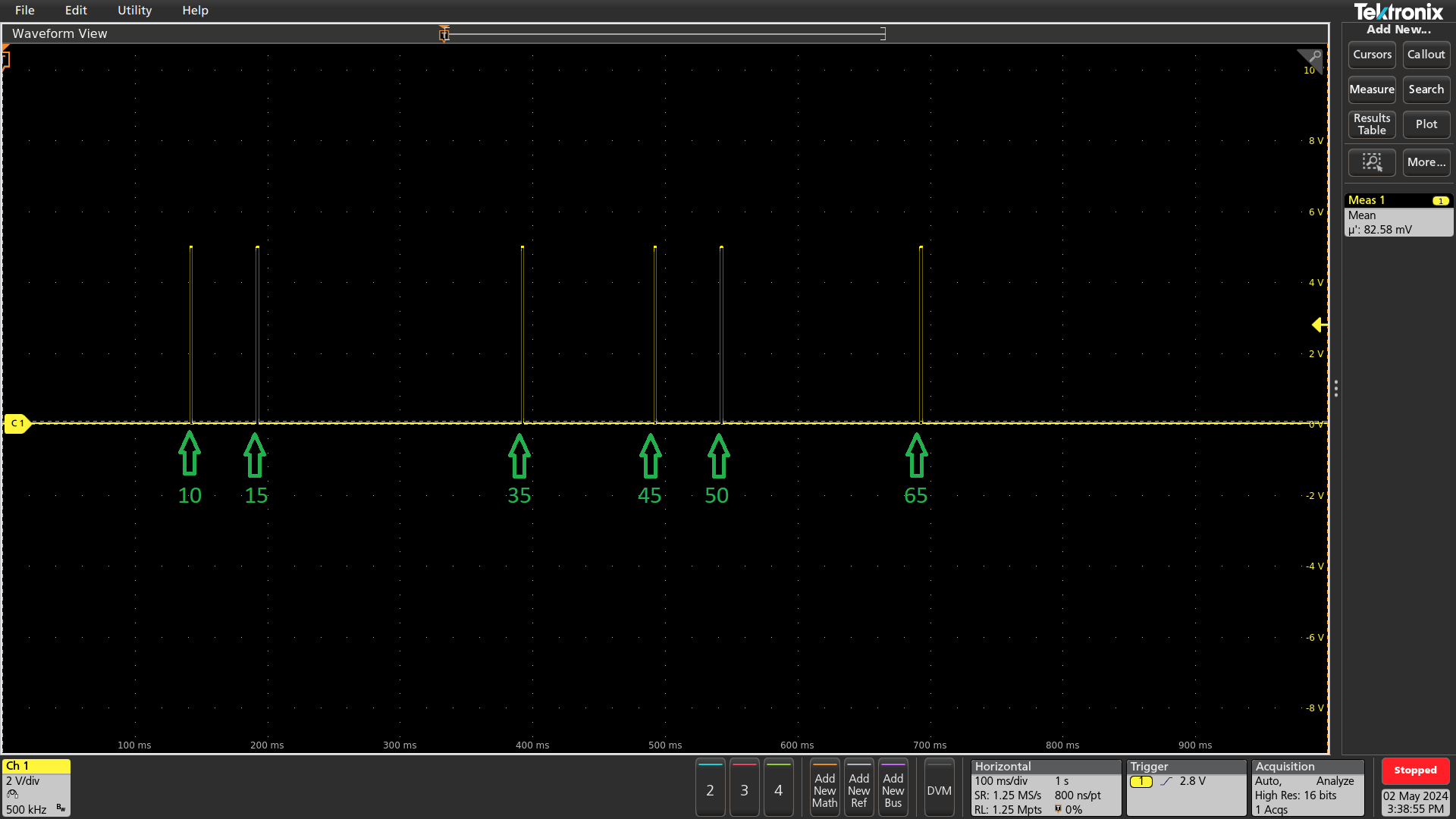
Array mode trigger generation hw scope measurement
Bidirectional interval mode
This example shows how to use two PBT modules to generate triggers on the same output, one for either direction. After crossing the ArmPosition the comparator is armed, and a single PositionMatch pulse is generated starting at the crossing of PositionStart and repeated for each crossing of PositionStart shifted by PositionStep in either positive direction (PBT 1), or negative direction (PBT 2).

Bidirectional interval mode trigger generation
The following XML configuration sets up Interval mode on 2 PBTs as described:
1 2 3 4 5 6 7 8 9 10 11 12 13 14 15 16 17 18 19 20 21 22 23 24 25 26 27 28 29 30 31 32 | <ProcessingBlock Name="PositionBasedTrigger1">
<Signal Name="Enable">0</Signal> <!-- ensure to disable PBT before writing all settings -->
<Signal Name="InputSelect">1</Signal> <!-- 1 = Enc1Position2, change if different encoder is used -->
<Signal Name="ExtrapolationSelect">2</Signal> <!-- 2 = Linear -->
<Signal Name="CompareSelect">1</Signal> <!-- interval mode -->
<Signal Name="ArmPosition">500000</Signal> <!-- 5mm in encoder counts -->
<Signal Name="PositionStart">1000000</Signal> <!-- 10mm in encoder counts -->
<Signal Name="PositionStep">1000000</Signal> <!-- 10mm in encoder counts -->
<Signal Name="NumberOfPositionMatches">6</Signal>
<Signal Name="DelayTime">0</Signal> <!-- 0 ns -->
<Signal Name="OnTime">2000000</Signal> <!-- 2 ms -->
<Signal Name="OffTime">0</Signal> <!-- 0 ns -->
<Signal Name="NumberOfTriggers">1</Signal>
<Signal Name="OutputSelectMask">0x1</Signal> <!-- 0x1 = RS485_TX_TOP -->
<Signal Name="Enable">1</Signal> <!-- enabling PBT after writing all settings -->
</ProcessingBlock>
<ProcessingBlock Name="PositionBasedTrigger2">
<Signal Name="Enable">0</Signal> <!-- ensure to disable PBT before writing all settings -->
<Signal Name="InputSelect">1</Signal> <!-- 1 = Enc1Position2, change if different encoder is used -->
<Signal Name="ExtrapolationSelect">2</Signal> <!-- 2 = Linear -->
<Signal Name="CompareSelect">1</Signal> <!-- interval mode -->
<Signal Name="ArmPosition">6500000</Signal> <!-- 65mm in encoder counts -->
<Signal Name="PositionStart">6000000</Signal> <!-- 60mm in encoder counts -->
<Signal Name="PositionStep">-1000000</Signal> <!-- -10mm in encoder counts -->
<Signal Name="NumberOfPositionMatches">6</Signal>
<Signal Name="DelayTime">0</Signal> <!-- 0 ns -->
<Signal Name="OnTime">2000000</Signal> <!-- 2 ms -->
<Signal Name="OffTime">0</Signal> <!-- 0 ns -->
<Signal Name="NumberOfTriggers">1</Signal>
<Signal Name="OutputSelectMask">0x1</Signal> <!-- 0x1 = RS485_TX_TOP -->
<Signal Name="Enable">1</Signal> <!-- enabling PBT after writing all settings -->
</ProcessingBlock>
|
The emphasized lines are specific for interval mode (e.g. both of the position comparator’s parameters). Running this example results in a scope plot as shown below.
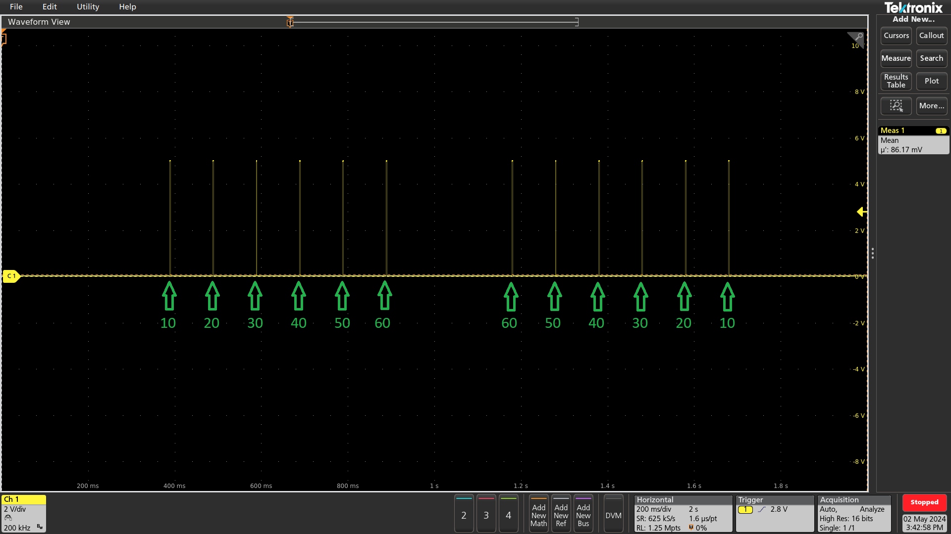
Bidirectional interval mode trigger generation hw scope measurement
Time based trigger generation
In this example a single PositionMatch pulse at PositionStart generated, which generates three assertions of Trigger on time based parameters:

Time based trigger generation
The following XML configuration sets up the time based mode on 1 PBT as described:
1 2 3 4 5 6 7 8 9 10 11 12 13 14 15 16 17 18 19 | <ProcessingBlock Name="PositionBasedTrigger1">
<Signal Name="Enable">0</Signal> <!-- ensure to disable PBT before writing all settings -->
<Signal Name="InputSelect">1</Signal> <!-- 1 = Enc1Position2, change if different encoder is used -->
<Signal Name="ExtrapolationSelect">2</Signal> <!-- 2 = Linear -->
<Signal Name="CompareSelect">1</Signal> <!-- interval mode -->
<Signal Name="ArmPosition">500000</Signal> <!-- 5mm in encoder counts -->
<Signal Name="PositionStart">1000000</Signal> <!-- 10mm in encoder counts -->
<Signal Name="PositionStep">0</Signal> <!-- 0 encoder counts -->
<Signal Name="NumberOfPositionMatches">1</Signal>
<Signal Name="DelayTime">0</Signal> <!-- 0 ns -->
<Signal Name="OnTime">20</Signal> <!-- 20 ns -->
<Signal Name="OffTime">30</Signal> <!-- 30 ns -->
<Signal Name="NumberOfTriggers">3</Signal>
<Signal Name="OutputSelectMask">0x1</Signal> <!-- 0x1 = RS485_TX_TOP -->
<Signal Name="Enable">1</Signal> <!-- enabling PBT after writing all settings -->
</ProcessingBlock>
<ProcessingBlock Name="PositionBasedTrigger2">
<Signal Name="Enable">0</Signal>
</ProcessingBlock>
|
The emphasized lines are specific for time based triggering (e.g. both of the trigger generator’s parameters). Running this example results in a scope plot as shown below.
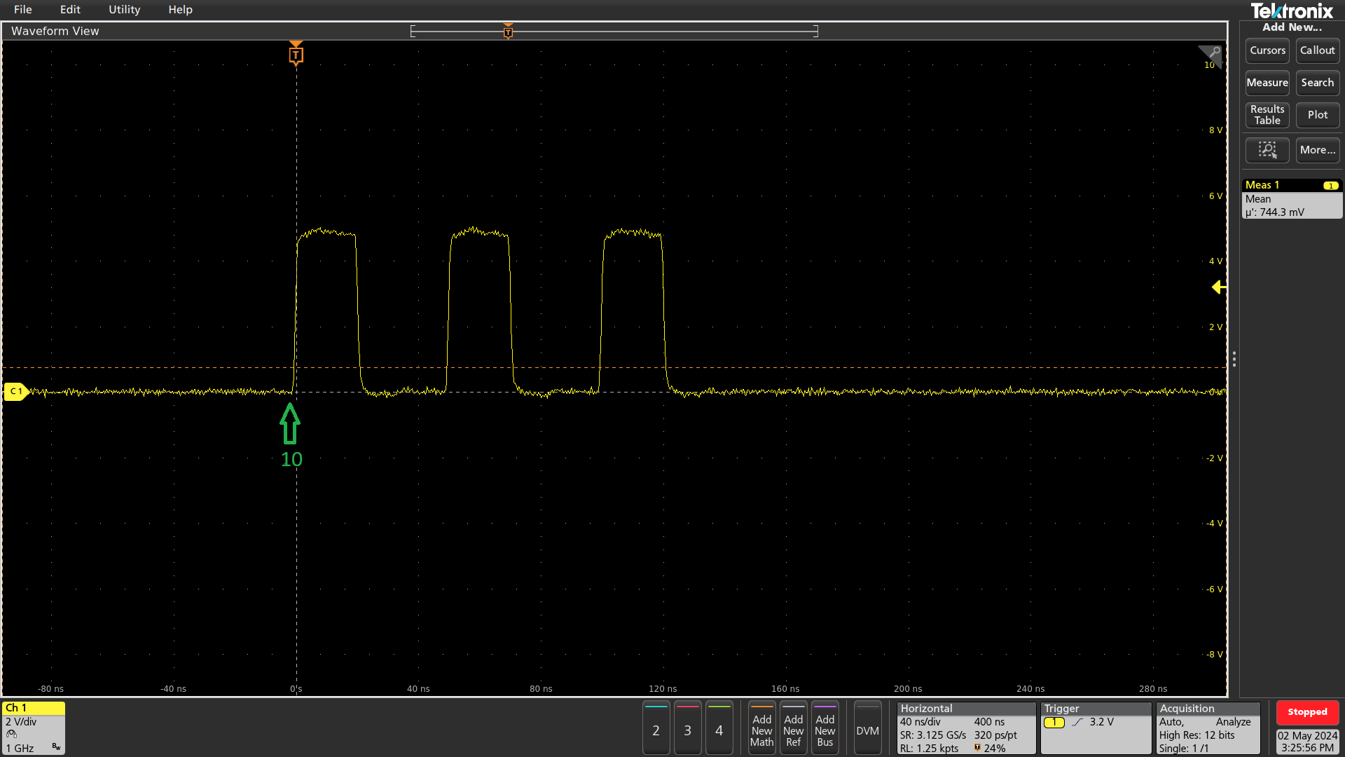
Time based trigger generation hw scope measurement