Create a simulator
PMP provides the ability to create a simulated system. Simulation can be used to simulate the behavior of a physical controller and plants for testing and validation. For instance, a customer can use a simulated system, which consist of a top-controller, a sub-controller and plant model that describes their system, to perform motion analysis before deploying it on physical hardware. The simulator can run on a client PC processor or can be deployed on a remote simulation server.
This guide provides step-by-step instructions on how to create a local simulated system with a top-controller and a sub-controller.
During this guide you will learn how to:
Use a system description file to create a simulated system.
Monitor the value of a signal using the Signal view.
Dispose of a simulated system.
Prerequisites
Before continuing with the quick-start guide, please make sure that the following prerequisites are met:
PMP should be installed with Simulator and Tooling features. Follow the Installation quick-start guide if this is not yet the case.
A Typical installation includes the required Simulator and Tooling features.The create a simulator quick start project files should be available. These files can be downloaded from Downloads.
- System description file:A system description file
system.xml, which describes the system properties and includes the controller’s description. - Controller description files:A top-controller (Arcas)
controller_arcas_5eg.xml, which describes the controller’s main properties, such as templates, number of axes, processing blocks, updatables, and more.A sub-controller (Arcas FPGA)controller_arcas_5eg_slave.xml, which includes digital IOs.
System description
The System description file system.xml defines the simulator properties and the simulated controllers that make up the simulated system.
The resulting system in visualized in Simulated system.
1 2 3 4 5 6 7 8 9 10 11 12 13 | <System>
<Properties>
<Property Name="SimulatorCpuUtilization" Value="Greedy" />
<Property Name="SimulatorRealTimeThreads" Value="2" />
<Property Name="SimulatorSpeedFactor" Value="1.0" />
<Property Name="SimulatorClientAddress" Value="localhost" />
</Properties>
<Controllers>
<Controller Description="controller_arcas_5eg.xml" HardwareSerialNumber="1" Id="1">
<Controller Description="controller_arcas_5eg_slave.xml" HardwareSerialNumber="2"/>
</Controller>
</Controllers>
</System>
|

Simulated system
Simulator creation
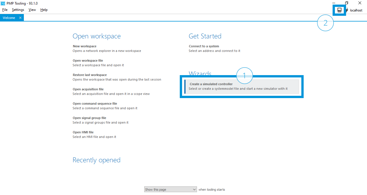
Start the PMP Tooling, and create a simulated system.
Select Create a simulated controller (1) or click the
 icon (2)
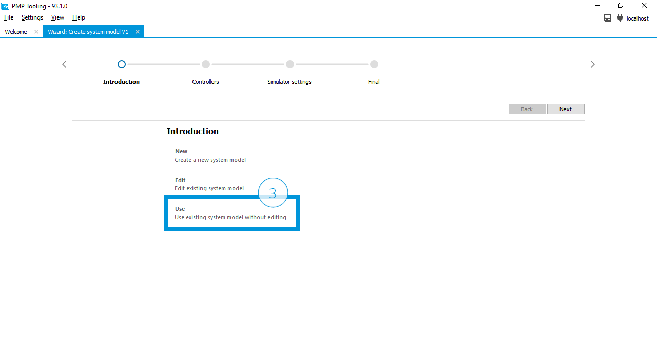
Select Use (3)
Select the system description file
system.xmlfrom the files system, andClick Start simulator (4)
Welcome view
Create simulator wizard
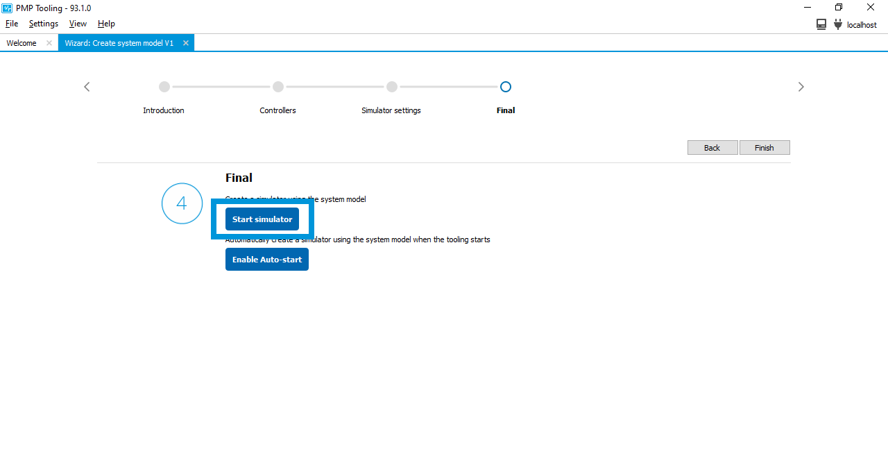
Start simulator
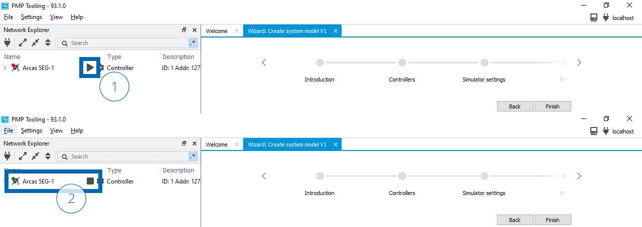
The simulated system is created based on the controller models defined in the system description file system.xml.
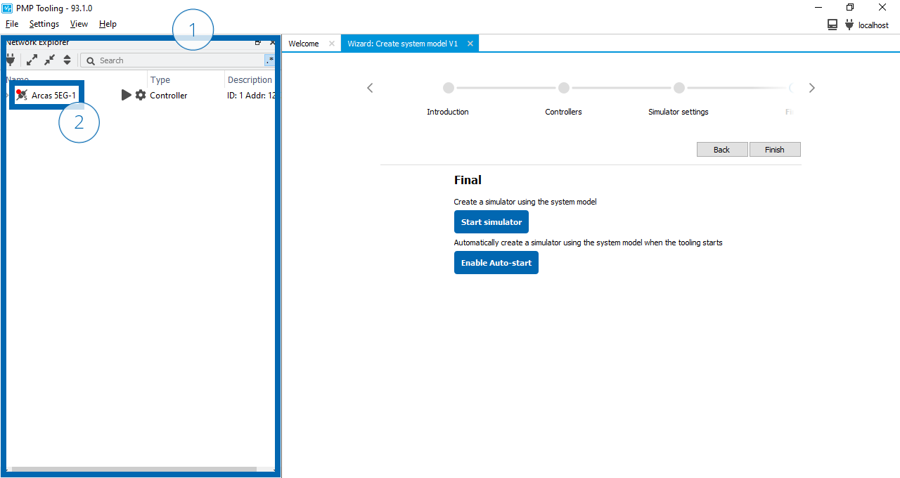
The Network explorer view will open automatically on the left side of the window (1), and
After simulator start-up the Arcas 5EG-1 will appear (2).
Note
Enumeration of the top- and sub-controllers can take some time depending on the complexity of the system and the amount of sub-controllers in the system.
Top-controller state machine
The top-controller is governed by the Top-controller state machine. Any controller, both physical and simulated, will automatically transition to the Config state. The current top-controller state can be seen in the network explorer by the indicator color next to the controller name.
In state Config, the indicator color is
 and the
  button is clickable.
In state Run, the indicator color is
 and the
  button is clickable.
In transition states Init, ConfigToRun, and RunToConfig the indicator color is
 and the buttons are disabled.
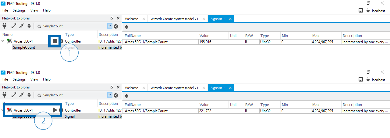
After the Arcas 5EG-1 appears, change the top-controller to Run state. In the Run state the periodic tasks are enabled and both periodic and asynchronous communication is possible.
Click the
button (1).Wait until the indicator color is
and the button changed to a button (2).
Change top-controller state to Run
Note
The Config to Run state transition can take some time depending on the complexity of the system and the amount of sub-controllers in the system.
Verification
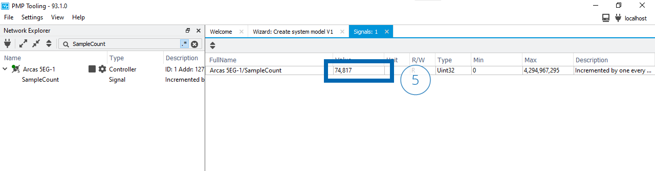
By default, the sample frequency of the Arcas 5EG-1 is 2kHz. To verify that the top-controller periodic tasks are enabled, monitor the incrementing of the SampleCount signal.
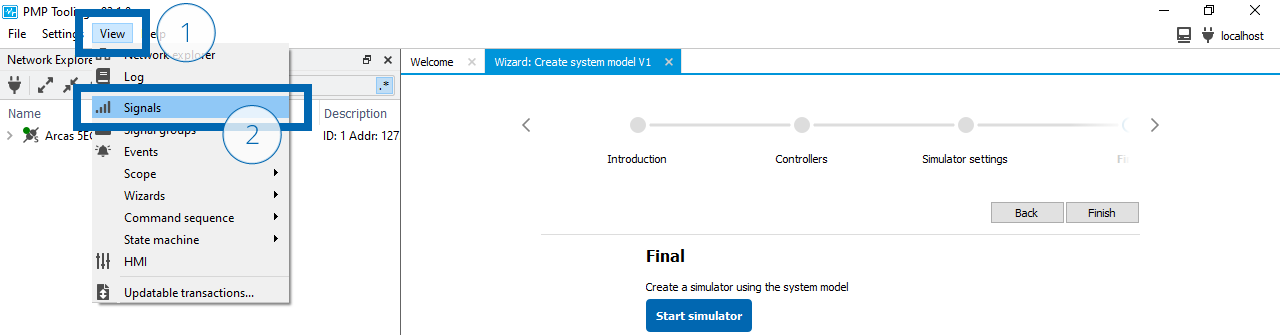
Open the View menu (1).
Select Signals to open a Signal view (2).
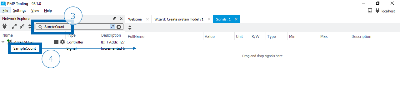
Type SampleCount in the search box of the Network explorer to find the SampleCount signal (3).
Drag the signal to the Signal view (4).
Verify the SampleCount increments with approximately 2,000 counts every second (5).
Note
The simulator is sample-accurate, but not time-accurate. This means that all samples are calculated as if the sample frequency is 2kHz, however the exact SampleCount increment per second can deviate from 2,000 counts per second based on the available performance on the computer the simulator is running on.
Clean-up
Now that the verification is completed we can clean-up the simulator.
Click the
button (1).Wait until the indicator color is
and the button changed to a button (2).Open the context menu of the Arcas 5EG-1 controller (3).
Select Destroy to destroy the simulator (4).
Change top-controller state to Config
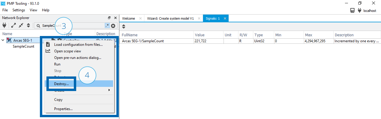
Clean-up simulator
Note
Closing the PMP Tooling does not destroy the simulator. The simulator keeps running until it is explicitly destroyed.
See also
- Simulation
Explanation of a system simulation concept and its purpose in the motion software.
- System description
For more information on system descriptions.
- Configuration
For more information on controller configuration.