Axis control
This chapter describes the AxisControl interface, which is a container for all functionality required to control an axis. See Axis control blocks for an overview of the blocks in axis control.

Axis control blocks
Command queue
An axis control has a queue for executing commands, e.g. to change state, perform movement, etc.
State machine
The software is designed to interface with modules that implement the standardized IEC 61800-7-201 control for power drives. The state machine determines which commands are accepted, e.g. move commands are only accepted when the state machine is in state Operation enabled. Additional to the user commands, internal event responders can influence the state of the state machine, see Event response.
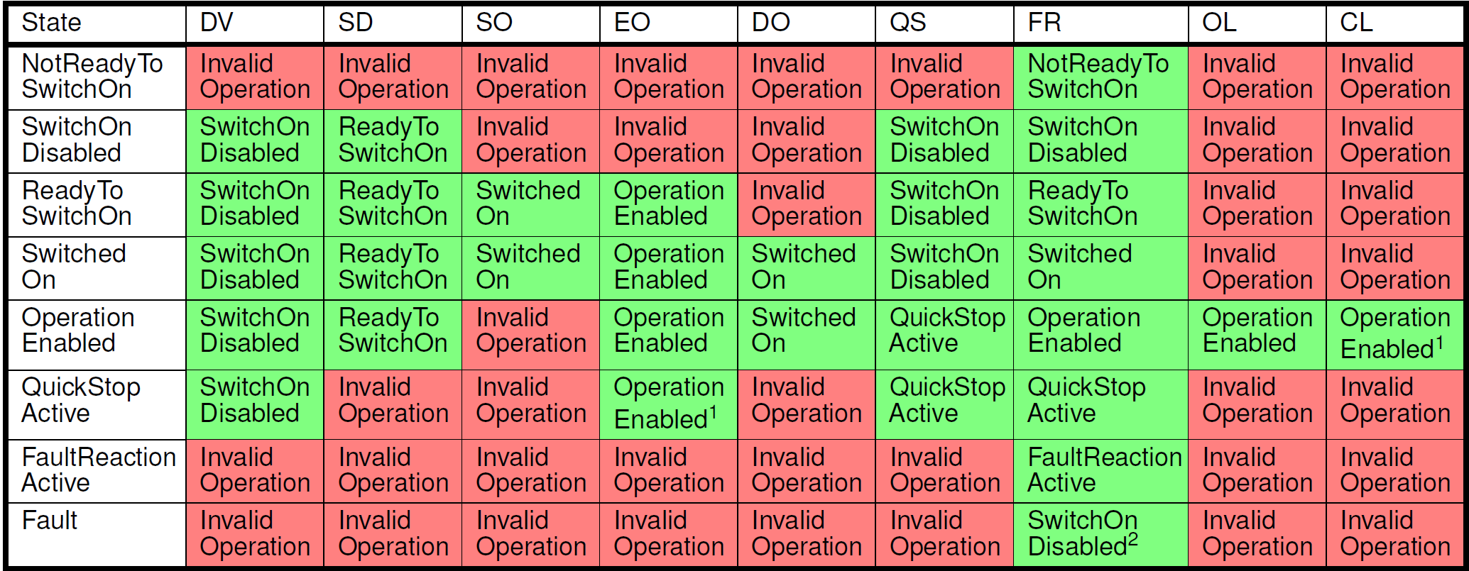
Axis control state machine shows the states of the state machine and what commands can influence them.

Axis control state machine
The following table describes the axis control states:
Axis control state |
Description |
|---|---|
Not ready to switch on |
The axis control is initializing. State transition requests are not accepted. Actuator supply voltage is disabled if per actuator supply voltage switching is supported by the controller. Automatic transition to the next state after initialization complete. |
Switch on disable |
Actuator supply voltage is disabled if per actuator supply voltage switching is supported by the controller. Use Shut down to go to the next state. |
Ready to switch on |
Actuator supply voltage is disabled if per actuator supply voltage switching is supported by the controller. Use Switch on or Enable operation to go to next states. |
Switched on |
Actuator supply voltage is enabled. Use Enable operation to go to next state. |
Operation enabled |
Actuator supply voltage and actuator are enabled. Move commands are accepted. Use Open loop and Close loop to switch between open and closed loop motion. |
Quick stop active |
Actuator supply voltage and actuator are enabled. Move commands are not accepted. After the Quick stop is completed, use Enable operation to resume operation. |
Fault reaction Active |
An event occurred that triggered an error response. Actuator supply voltage and actuator are in the same state as the previous CiA402 state. Automatic transition to the next state after additional configured responses, e.g. Quick stop, is completed. |
Fault |
Actuator supply voltage is disabled if per actuator supply voltage switching is supported by the controller. Use Fault reset to attempt to recover. |
The following table describes the abbreviations of the different state transitions:
Abbreviation |
Command |
Remarks |
|---|---|---|
SD |
Shut down |
|
SO |
Switch on |
|
DV |
Disable voltage |
|
QS |
Quick stop |
|
DO |
Disable operation |
|
EO |
Enable operation |
Additionally performs Switch on if necessary. |
FR |
Fault reset |
|
OL |
Open loop |
|
CL |
Close loop |
The following table describes the allowed device control commands:
Allowed device control commands
Note
Throws Invalid operation exception if trajectory state is not InPosition, i.e. trajectory interpolator is active.
State remains Fault if events with configured error response are active.
Trajectory generator & interpolator
Typically an axis control contains a Trajectory generator and a Trajectory interpolator.
Signals
Remaining axis control related signals are shown in the following table:
Name |
Data type |
R/W |
Description |
|---|---|---|---|
IsPaused |
Bool |
R |
Axis control paused status signal. Indicates that an axis control is part of an axis control group and paused. |
SampleCount |
UInt32 |
R |
Incremented every sample of the axis control loop. The value is cleared on power-on reset. The application must handle possible counter overflows. For example when the sample rate of an axis control is 4 kHz, the counter overflows in approximately 12 days. |
SamplePeriod |
Float |
R |
The interval at which the loop of this axis control is calculated. |
Event
An axis control is also an event source and an event responder.
Response priority and ordering
Response priority and ordering is handled as follows:
If multiple responses are configured for a single event the responses are executed in the order as stated in product specific documentation (starting from 1).
If different responses are requested by multiple events (from single or multiple event sources), the highest priority (starting from 1) response in the request overrules the lower priority active or requested responses.
Responses without a defined priority and order are always executed regardless of other active responses or requests.
For example (see Event response requests example flow): Event A configured to QuickStop and DisableVoltage responses, and event B is configured a DisableOperation response. If event A occurs a QuickStop` –> DisableVoltage is executed sequentially. However, if in the meanwhile event B occurs the QuickStop originating from event A is overruled and DisableOperation is executed.

Event response requests example flow
Root error behavior
When the axis control supports an error response, events configured for this response have the additional feature that the first event is latched and stored internally as the root error. The root error remains latched until ResetFault is called.
See also
- AxisControl
XML configuration example of the axis control interface.